
US 201855
UNITED STATES PATENT OFFICE.
ROLLIN WHITE, OF LOWELL, MASSACHUSETTS.
IMPROVEMENT IN. CHARGING MAGAZINES FOR REVOLVERS.
Specification forming part of Letters Patent No. 201,855, dated March 26, 1878; application filed February 27, 1878.
To all whom it may concern:
Be it known that I, Rollin White, of Lowell, in the county of Middlesex and State of Massachusetts, have invented a new and useful Improvement in Magazines for Fire-Arms; and I do hereby declare that the following is a full and exact description of the same, reference being had to the accompanying drawings, and to the letters of reference marked thereon.
In the use of fire-arms for military purposes by cavalry, where the time for effective use of the same is usually very short, and where for that reason revolvers appear to be preferred, it has been found very difficult to recharge the cylinders after they have been emptied by discharges, on account of the necessity of employing one of the hands in guiding and managing the horse, on account of the irregular movements or motions of the animal, and frequently on account of the numbness of the fingers in cold weather. For these reasons, as well as on account of the mental excitement in actual conflict, it usually happens that in a charge of cavalry the chambers of the revolvers are discharged at once, and then reliance is had upon the saber, or else the horsemen fall back and come to a halt for the purpose of recharging.
The object I have in view, then, is to provide a magazine especially suited for revolving fire-arms, adapted to be secured to the body of the horseman, capable of holding in a secure manner, protected from exposure to injury, a large number of charges of ammunition, and having contrivances by means of which all the chambers of a revolver may be charged instantly under all circumstances and in any sort of weather.
The novelty in my invention consists, principally, in a magazine adapted to be carried on the body, and capable of charging all the chambers of a revolver at the same instant, and in the novelty of the various essential parts, and in their various operative combinations, all as will be more fully hereinafter described and explained.
In order that those skilled in the art may know how to make and use my magazines, I proceed to describe the same, having reference to the accompanying drawing, making a part of this specification, in which—
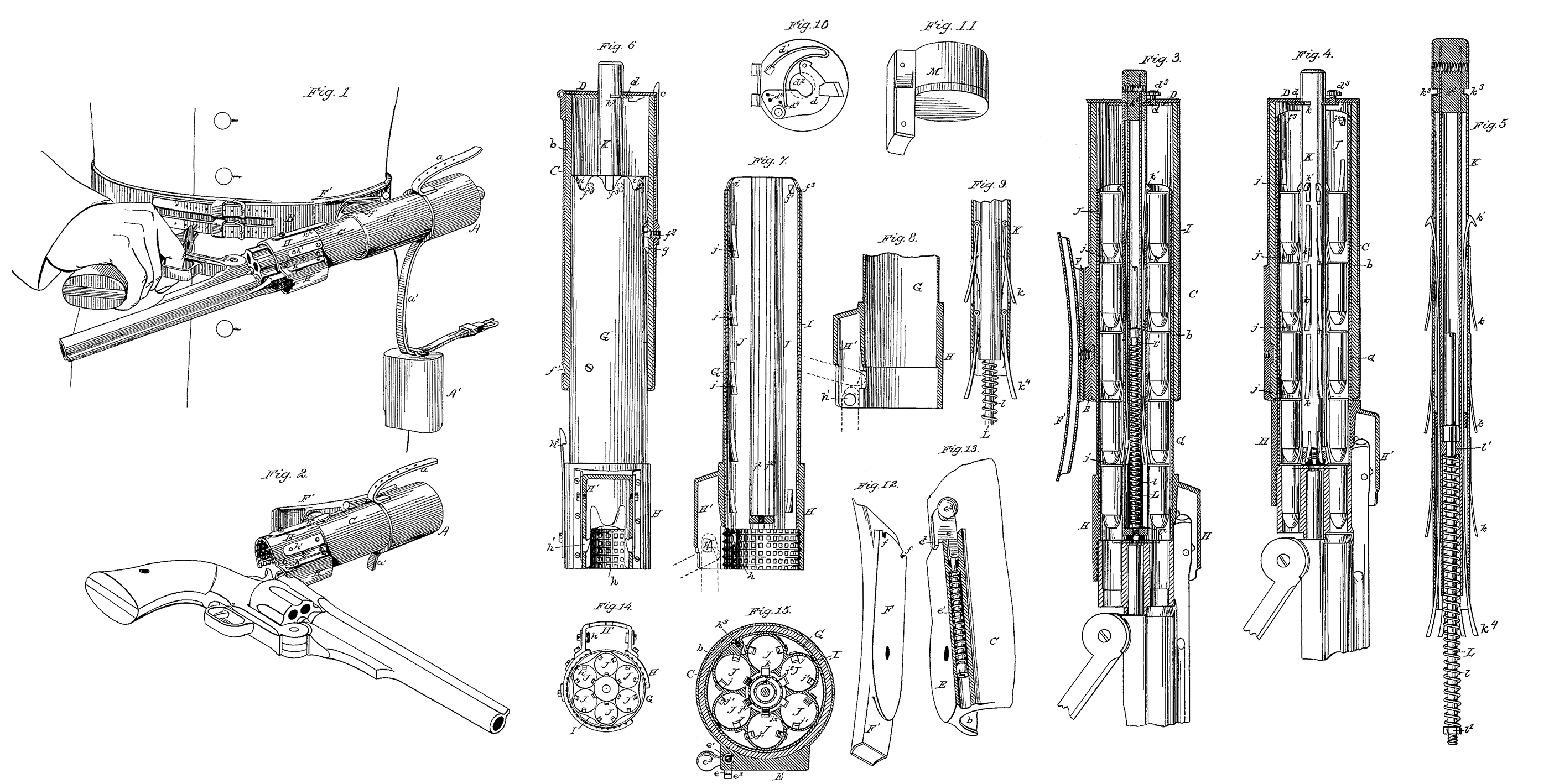
Figure 1 is a view of my magazine attached to the body of the wearer, showing the mode of charging the cylinder of a revolver; Fig. 2, a view of the magazine, showing the position of the revolver after the cylinder has been charged and the pistol has been closed up for use; Fig. 3, a central vertical section of the magazine with the cylinder of the revolver within the open end of the magazine before the act of charging the cylinder; Fig. 4, a similar section after the cylinder has been charged; Fig. 5, a similar section of the plunger and its various operative attachments; Fig. 6, a view of the magazine, showing the inner shell in elevation, the outer shell in vertical section, and the charging-guide in elevation, except that portion of it which receives the projection of the barrel, which portion is in section; Fig. 7, a vertical central section of the inner shell and the charging-guide; Fig. 8, a modification of Fig. 7; Fig. 9, a modification of Fig. 5; Fig. 10, an inside view of the cap or cover to the magazine; Fig. 11, a view of the plug to close the open end of the magazine; Fig. 12, a view of the swivel-plate to which the belt is attached; Fig. 13, a view of the swivel-plate attached to the magazine, With a part broken away to show the enclosed spring; Fig.14, a bottom-end view of the magazine; and Fig. 15, a central cross-section of the magazine.
Like letters denote corresponding parts.
In the drawings, A and A’ represent the leather cases which cover the opposite ends of the magazine; a, a short strap, secured to one of the leather cases; and a’, another strap, secured to the same leather case, with its buckle end passing over the outer end of the other case through a suitable guide, so that the end of the strap a may pass through such buckle, and the two cases A A’ be drawn toward each other, and held respectively at the desired distance apart. The opposite end of the strap a’ is secured to the belt B, so that the cases and the magazine enclosed in them may hang, if desired, at a convenient distance below the belt. This belt B is made in any convenient way, and adapted to be worn around the waist; but it is apparent that any shoulder-belt, or other convenient means of support, may be used; or the magazine may be attached to the body of the wearer in any convenient way; or the magazine, with or without leather cases, may be carried in a holster, or in some sort of cartridge-box, or in a knapsack or haversack, it being only desirable that it should be at instant command for use.
As shown in the drawings, and as the preferable mode, the magazine is secured directly to the belt.
The magazine is composed of several distinct parts, which will be described in order, it being observed that the peculiar magazine, as illustrated in the drawings, is designed for use with a revolver of the Smith & Wesson type.
The outer shell C is a cylinder, made of any proper material, preferably of sheet metal, which has, preferably, a packing-lining, b, of leather or other suitable material; or, indeed, the packing may be used without any shell. To the top of this shell C is hinged a cap or cover, D, which, when closed, is held fast by a spring-latch, c. Upon the inside of this cap or cover (shown particularly in Fig. 10) is a hook, d, actuated by a spring, d^1, which hook is adapted to engage with a slot or score in the plunger, hereinafter to be described, and to hold the same in position. This spring d^1 is shown with its free end inserted in holes d^4, where it operates the hook, as described; but the free end may be inserted in the other holes d^5, in which case the hook is held constantly back out of position of engagement. This plunger passes through a proper opening, d^2, in the cap or cover. The hook d is actuated from the outside of the cap or cover by a proper stud, d^3. Upon the outside of the shell C is secured a swivel-plate, E, having a suitable pivot, which plate has a hollow space under it, for the reception of a lock, e, which lock has a spiral spring, e^1. Upon the head of this lock is a hook, e^2, adapted to engage in the periphery of the swivel-plate F of the belt, so as to hold the magazine at any convenient angle, and this lock is operated by means of a suitable stud, e^3.
The swivel-plate F is pivoted upon the swivel-plate E in any convenient method, and its periphery is notched, as at f, for engagement with the hook e^2. This plate F is secured to a convenient sliding clasp, F’, through which the belt B may be threaded; or the belt may be threaded through a loop attached to the magazine. Upon this shell C there is a suitable notch, f^1, for engagement with a spring-latch, hereinafter to be mentioned. In the same shell, also, is inserted a proper screw-pin, f^2, which extends into its interior, and, passing into a slot, g, upon the inner shell G, limits its movement back and forth to the extent of the length of such slot.This inner shell is scalloped at its top, as shown by f^3.
The inner shell G is made of proper material, preferably thin sheet metal, and is designed to fit closely into the interior of the shell C. It may be made cylindrical or polygonal in whole or in part, and has on one side of it a slot, g, into which the pin f2 enters, as explained above, and limits its movement back and forth, and prevents its rotary movement. Upon the outer end of this shell is secured the charging-guide H, made of a size and form to receive into its interior the cylinder of the revolver to be charged; and it has upon one of its sides a portion, H’, made of a size and form to admit of the reception within it of the projection of the barrel of the pistol, or that part which locks the pistol-barrel to the recoil-shield. This guide H H may be made a little flaring at its mouth for more convenient use. Upon the side of this portion H’ is a spring-latch, h, which engages in any suitable way with the projection of the barrel when the pistol is so far withdrawn after charging as to withdraw the cylinder from the magazine, and holds the pistol until it is turned into proper position for locking. The interior of the guide H may be roughened, as shown at h, so that if dirt or dust should find its way in it would not obstruct the entrance of the cylinder. Upon one of the sides of this shell G is a spring-detent, h^1, the office of which is to fit into the longitudinal slot or recess for the locking-bolt which is found in the cylinders as constructed, and serves to hold the chambers of the cylinder in line with the chambers of the magazine. Upon the same shell G is a spring-latch, h^2, which engages with the notch f^1 upon the shell C, and holds the two shells together.
Within the shell G, and secured to it by suitable means h^3, is fitted the ammunition-case I, made preferably of thin sheet metal, and composed, in this instance, of six tubes, J J J, arranged around a central plunger and secured together; but the whole case may be made of solid metal, like a cylinder, and properly bored out. In these chambers J J are inserted springs j j, extending into the interior of such chambers, with their free ends pointing toward the loading end of the magazine, and of these springs four are shown in the drawing, the ends of such springs being apart the full length of a cartridge. Instead of a spring, for economy of space a spring-hook, j^1, is placed at the upper end, or the end opposite the loading end of each of the chambers J J. These springs j j and hooks j^1j^1 serve to hold the cartridges from moving backward in their progress toward the loading end, and also to prevent their dropping out.
It is evident that, instead of such springs, pawls or tooth-bars, or other equivalent devices operating in the same way, may be employed. In the interior of each chamber J J, nearest toward the center of the case I, are longitudinal slots j^2 j^2, in which traverse springs k k and hooks k^1 k^1, secured to the plunger K, similar to the springs j j and hooks j^1 j^1. Placed centrally within the case I, and centrally as to the chambers J J, is the plunger K, which is a metallic tube, the top of which, k^2, is solid for a short, distance, in which part is cut a groove, k^3, with which the hook upon the cap engages. In the lower interior part of this plunger is secured a rod, L, having around it a suitable spiral spring, l, which extends from a shoulder, l^1, in the tube to a nut, l^2, or shoulder on the bottom of the rod, into which the rod is screwed. The lower series k^4 of these springs is secured within the interior of the plunger and-bent outwardly below its lower end, at which point they are thicker and stronger. When these springs strike upon the base of the cartridges to drive them home into the cylinder they ride upon the nut or shoulder on the bottom of the rod L, and effectually prevent the next series of cartridges from dropping down until the plunger is withdrawn to charge again.
The top of the ‘ammunition-case I is scalloped, as at i, to correspond with the scalloped portion f^3 of the inner shell G, for the purpose of pressing the cartridges into the chambers J J more conveniently, when filling such chambers by hand.
The construction of the magazine is complete with the addition of the plug M, made of any suitable material, and adapted to fit closely into the interior of the charging-guide H H’, in which it is held by friction and by the pressure of the springs connected with such charging-guide H H’; or it may be locked in place by one or more of such springs. This plug not only excludes dust and moisture, but it assists in holding the cartridges from falling out.
The manner of operation of the various parts of my magazine, and of the entire magazine, is now described, it being premised that the magazine is supposed to have been filled by hand with cartridges thrust in from the top, one by one, until each of the ammunition-chambers is full, as shown in Figs. 3 and 4, and it being also supposed that a horseman is carrying the magazine attached to his belt, as shown in Fig.1. The magazine being turned into a convenient position upon its swivel, the meeting faces of the plates of which may be packed with any suitable material to prevent the intrusion of dust and water, and to better retain any lubricant, and the plug being removed, the magazine is now ready for charging the revolver. The horseman holds his revolver, which is supposed to be unloaded, with his right hand, with the usual grasp for firing, breaks it down with the same hand, thus exposing the end of the cylinder in the usual way for loading, disengages the spring-latch h^2, when the inner shell slides out by the action of the spiral spring in the plunger, and then thrusts the end of the cylinder and the projection of the barrel into the charging end of the magazine, as shown in Fig. 1. When the cylinder is locked, when thrown open, as in some instances, by a spring-stop upon the projection, the chambers of the cylinder will be in line with the ammunition-chambers of the magazine. In instances where the cylinder is not thus locked, it will be necessary to revolve the cylinder until the spring catch or detent h^1 gets into position, which will arrest the cylinder in line with the ammunition-chambers.
The cylinder being inserted, as described, in the charging end of the magazine, is locked therein by means of the spring-latch h^1, and force being then applied by the hand holding the pistol, the cylinder is pushed back, in turn pushing the inner shell G into the outer shell until the two shells are locked together by means of the spring-catch h^2. At the same instant the springs k k upon the plunger K force a cartridge from each chamber of the ammunition-case into the corresponding chambers of the cylinder, as is shown in Fig. 4. The cylinder is then withdrawn, and, the projection of the barrel being held by the spring-latch, swings upon the same in the act of closing up the pistol, and at the same time as the line of direction of the barrel is changed in the act of closing up the projection is released and readily comes out of the charging end of the magazine.
If it is desired to charge the cylinder of the revolver by operating the plunger alone, which may be done as well with the leather case on as when it is removed, the plunger passing through the end of such leather case, as shown in Fig.1, it is necessary to release the end of the plunger from the hook d upon the cap D, when the plunger will protrude a sufficient distance. In this case, however, the spring latch h^2 remains in position, holding the outer and inner shells together. Then, by pressing the cylinder inwardly after it has been entered into the charging end of the magazine, and allowing the end of the plunger to come in contact with the left arm, the cartridges will be forced down into the cylinder, as before described; or the end of the plunger may be struck with the left arm or the left hand.
It will be perceived in the operation of this plunger that the hooks k^1 carry along the upper series of cartridges, while the ends of the springs k k force down each of the other series of cartridges at the same time that the springs j j prevent the cartridges from being moved out of place upwardly by any agitation or jolting of the magazine, while the springs k k, bending inwardly under the fronts of the cartridges, prevent their movement in the opposite direction.
It will be observed that the lower series k^4 of the springs of the plunger K are fastened to the interior of the plunger, and are stouter than the other springs, k, and serve better their purpose of driving the cartridges home in the chambers of the cylinder, and they also prevent the next series of cartridges from coming Out,
In the modification shown in Fig. 8 it will be observed that, instead of the spring-detent h^1, (shown in Fig. 7,) there is a stud in the charging end, adapted to engage with a corresponding stud or equivalent in the projection. It will also be observed that in Fig. 9 is shown a modification of the springs k k^4 by the use of pawls.
It is to be observed that, while I have described particularly my mode of construction, I do not intend to be restricted in such details, as in the actual construction of my magazine for use it will be deemed advisable to simplify details to the largest extent.
The magazine may be charged by hand by inserting the cartridges one by one into the ammunition-chambers; or a separate charger can be used for this purpose, for which I am about to apply for Letters Patent.
Having thus described my device and explained its use, I do not mention its advantages, which are self-evident, but claim therein as new and of my invention—
1. A magazine, substantially as shown, adapted to charge all the chambers of a fire-arm at the same time, substantially as described.
2. A magazine, substantially as shown, capable of holding many charges of ammunition, and adapted to charge all the chambers of a revolver at the same time, substantially as described.
3. A magazine adapted to be secured to the belt of a person, with a swivel-connection, so as to be capable of presentation at any desired angle, substantially as described.
4. A magazine, substantially as shown, adapted to receive and retain in place the cylinder of a revolver while the same is loaded from the magazine, substantially as described.
5. A magazine containing an ammunition-case, provided with chambers corresponding to the chambers in the cylinder of a revolver, substantially as described.
6. A magazine or an ammunition-case having a plunger, by means of which all the cartridges for one charge of a cylinder are ejected at one time, substantially as described.
7. A magazine or ammunition-case provided with means to eject one series of cartridges at a time, and to hold the remaining cartridges from movement in any direction, substantially as described.
8. A magazine or ammunition-case provided with means, substantially as shown, to hold its chambers in line with the chambers of the cylinder in the act of charging, substantially as described.
This specification signed and witnessed this 19th day of February, 1878.
ROLLIN WHITE.
Witnesses:
A. B. Kelly,
L. W. Seely.