
US 250375
To all whom it may concern :
Be it known that I, Wm. Mason, of Hartford, in the county of Hartford and State of Connecticut, have invented a new Improvement in Revolvers; and I do hereby declare the following, when taken in connection with the accompanying drawings and the letters of reference marked thereon, to be a full, clear, and exact description of the same, and which said drawings constitute part of this specification, and represent, in—
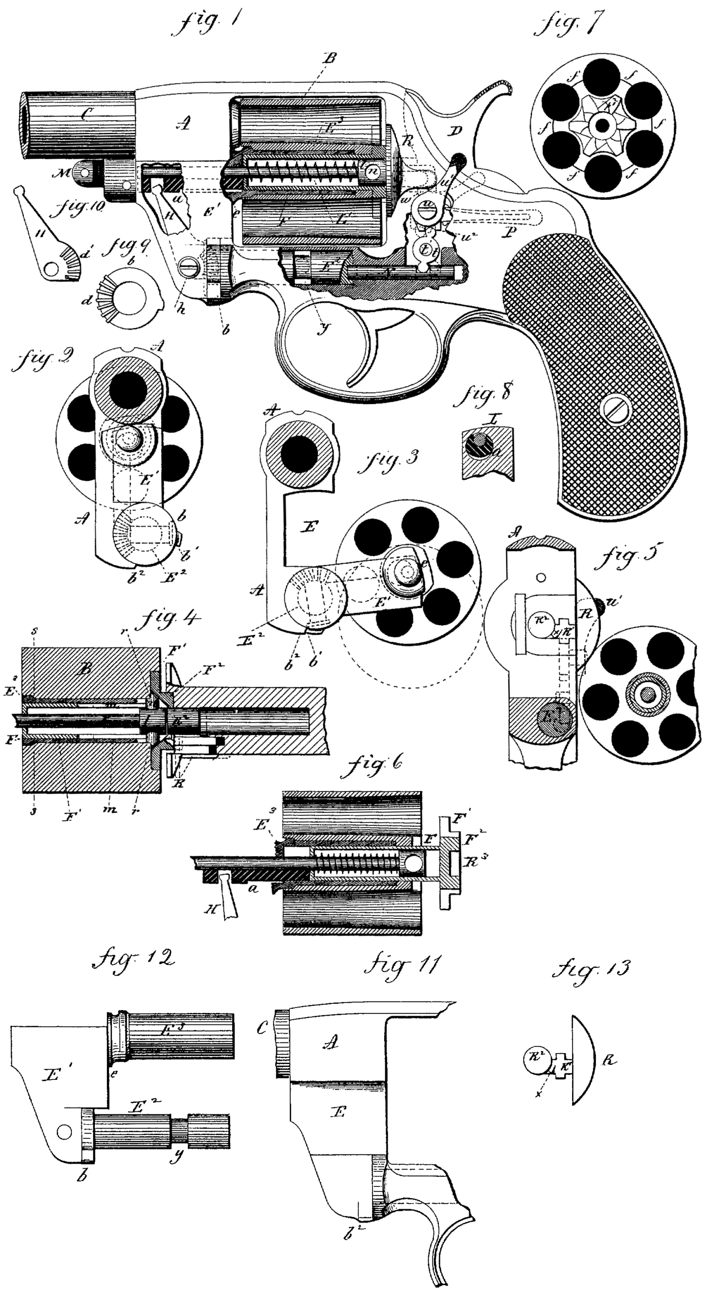
Figure 1, a sectional side view ; Figs. 2 to 13, inclusive, detached views.
This invention relates to an improvement in revolvers, and particularly to that class in which the cylinder is arranged to swing outward from its place in the frame, so as to expose the chambers in the cylinder for the insertion and removal of the cartridges or shells, the object of the invention being to provide an ejector which shall automatically operate to simultaneously throw all the shells or cartridges from the cylinder which may be in the chambers when it is turned outward from the frame; and the invention consists, essentially, in constructing a part of the frame to serve as the center-pin on which the cylinder revolves, the said part arranged to swing on a pivot, the axis of which is parallel with the axis of the cylinder, combined with an ejector arranged at the rear end of the cylinder to engage the heads of the several cartridges, and mechanism Operated by the outward-swinging movement of the part of the frame which supports the cylinder, to give to the ejector the rear movement to force the shells or cartridges from their respective chambers, and also in details of construction more fully hereinafter described, and particularly recited in the claims.
A represents the frame or receiver, of substantially the usual outline, constructed with a recess for the cylinder B, and provided with the barrel G, hammer D, aud lock mechanism, substantially in the usual manner, whereby the cylinder is rotated to successively present the cartridges introduced into the chambers in line with the barrel for discharge. In the part of the frame forward of the cylinder a recess, E, is made in one side, as seen iu Figs. 3 and 11, extending from the cylinder-opening to the forward end of the frame to receive the swinging part, or what I term the “ crane,” E’. (Seen detached in Fig. 12.) This swinging part is provided with a spindle or pivot, E2, parallel with the axis of the cylinder, and which enters and fits a corresponding seat in the frame below the cylinder-opening, and so tha,t it may readily turn on said pivot E2, as from the position in Fig. 2 to that indicated in Fig. 3.
On the swinging part E’, above the pivot E2, parallel with it and concentric with the cylinder, is the center-pin E3, which forms the bearing on which the cylinder turns. This pin is made tabular or hollow, as seen in Fig. 1, for the purpose hereinafter described. At the junction of the pin and the swinging part E’, I form a projection or shield, e, which will overlap the adjacent part of the frame and prevent gas from enteriug at the joiut. The cylinder is fitted upon its center-pin or bearing E3 so as to turn freely thereon, and the relation of the parts is such that when the swinging part is closed, as in Fig. 2, the cylinder is in its place of rest in the frame; but when the swinging part is turned away, as in Fig.3, the cylinder moves out from its place in the frame sufficiently far to expose the chambers for the insertion or removal of the cartridges or shells.
Within the center-pin E3 the ejector-rod F is arranged so as to move longitudinally therein, and substantially concentric with the center-pin and cylinder. On the outer endof this ejector-rod the ejector-plate F’ is arranged. This plate is of star shape, its arms / (see Fig. 7) extending outward between the respective chambers, and so that when in its place in a recess in the rear end of the cylinder, as seen in Fig. 4, the said arms or part of the ejector-plate will lie at the rear edge of the chamber, so that the heads of the cartridges inserted therein, or a portion of each, will rest on the said plate, so that when the ejector is thrown outward, as seen in Fig. 6, it will force the cartridges or shells from the chambers of the cylinder. This star-shaped ejector is well known, and requires no further description in this specification.
The ratchet F2, by which the cylinder is rotated, is attached to or made a part of the ejector-plate, as seen in Fig. C. To give the ejector the required rearward movement as the cylinder is turned outward, a follower, a, is arranged in theswinging partE’ parallel with the axis of the cylinder, and in line with the ejector-rod F and bearing against its forward end, as seen in Fig. 1. For the purpose hereinafter described, this follower a is made eccentric to the center-pin against the ejector-rod, as seen in Fig. 6, so that the rear movement of this follower a will correspondingly force the ejector rearward, as from the position in Fig, 1 to that seen in Fig, 0.
Loose on the pivot E2 is a ring, b, (seen detached in Fig. 9,) which is free to turn on the spindle, yet will turn with it when the part E’ swings outward or inward.
On the forward face of the riug b is a bevel segment-gear d, and forward of this riug, in theswinging part E’, an arm is hung upon a pivot, h, the axis of which is at right angles to the axis of the ring. This arm is shown detached in Fig. 10.
At the lower end of the arm H, and concentric with its pivot, is a segment, d’, eorre-sponding to and so as to work iu the teeth d of the ring b. Their relative arrangement, as seen in Figs. 1 and 2, is so that their toothed portions d d work together like a pair of bevel-pinions; but instead of such gear-like teeth other devices may be employed to engage the arm.
As seen in Fig. 1, the arm H is iu its extreme forward position—that is, in place, with the ejector home. When the swinging part E’ is turned outward, as before stated, the ring b will turn with it, the center of motion of the swinging part being the axis of the ring. If, therefore, the movement of the ring b be not interrupted, it can have no effect whatever upon the arm H; but if during the swinging movement the ring & be stopped,then, the swinging movement continuing, the teeth W of the arm H, which are swinging upon the same center as the swinging part, will be forced to travel through the then stationary teeth d on the ring, which will impart to the arm H a movement on its center corresponding to the movement of the swinging part on its center, which will turn the arm H rearward, as from the position in Fig. 1 to that seen in Fig. 6, in a plane parallel with the axis of the cylinder. The rear movement of the ejector most not occur until after the cylinder has been turned so far from the frame that the heads of all the cartridges are exposed outside the frame, and that its movement may commence at such time a shoulder, is made on the periphery of the ring b, and a corresponding shoulder, b9, on the frame below, so that as soon as the shoul-ler b’ on the ring strikes the shoulder b9 on ;he frame the further turning of the ring b fvill be arrested. Then as the swinging part sontinues its movement to the position, say, as ndicated in broken Hues, Fig. 3, the ring will •emain station ary and thearmH will be turned, as before described, because of its engagement with the riug, from the position in Fig. 1 to that seen iu Fig. 0, and force the ejector rearward from the cylinder, as seen iu Fig. G,
To automatically return the ejector and the arm H, I provide a spring within the ejector-rod, which is made hollow for this purpose, as seen in Fig, 1, To apply this spring a spindle, L, is arranged through the swinging part concentric with the cylinder, and, extending through the ejector rod, is provided with a head, 7, of the internal diameter of the ejector-rod, the spindle itself being of smaller diameter, and so that the spring L’ may work in the space between the ejector-rod and the spindle L,one end bearing rearward against the head Ion the spindle, the other end bearing against aseaton the interior of the ejeetor-rod, as seen iu Figs. 1 and G. The spindle being stationary, the rear movement of the ejector, as before described, presses the spring, as seen in Fig. G; hence so soon as the swinging part begins its return the spring reacts, throwing forward the follower a and the arm H, so that they will arrive at their closed position when the swinging part has been returned to the point where the engagement of the shoulders b’ and b2 was made; then from that point the continued closing movement turns the ring back to its place of rest, or point from which it started. Thus the simple act of throwing theeylinder outward causes the ejector to move rearward and eject the shells from the cylinder.
The follower a is made ecceutric to the center-pin to avoid cutting away so much of the swiuging part as would be necessary if it were made concentric, because the spindle L must be concentric, and if the follower be made iu the form of a sleeve to surround the spindle it would necessarily cut away the swiuging part above the spindle,; hence Iarrange iteeoenlric, and make a longitudinal groove in its upper surface,within whichthespindle Lrests, sothat no portion of the swinging part is cut away above the spindle, the spindle lying eutirely within the periphery of the follower, as seen in Fig. 8. The arm H engages the follower by means of the said arm, and within which that end works. ,
To prevent the ejector turning upon its center and thereby changing its proper relative position to the chambers, I make a longitudinal slot, m, (see Fig. 4,) in the ejeetor-rod, preferably upon opposite sides, and through the head Zof the spindle L, I place a pin, n, as seen in Fig. 4, which will extend into the slots in the ejfector-rod, but so that the slots in the rod will permit itto pass freely out or in, guided by said pin, and this pin I also employ to hold the cylinder in place in its bearing by extending the ends of the pin, as seen in Fig. 4, onto the rear surface of the cylinder, as at r, Fig. 4, the cylinder butting against the shoulder s near the forward end. The shoulder s at the forward end and the pin r at the rear end prevent longitudinal movement of the cylinder. Thespiu-dleL, with its head and pin, is therefore introduced at the rear end forward through the cylinder and ejector, and when in itsplaceof rest is secured at its forward end by a nut, M, or otherwise, so that when it is desirable to remove the cylinder from its pin or the ejector, release the spindle at the front, and it is free to be drawn out rearward for the removal of said parts.
It is desirable to automatically lock the s win g-iug part when the cylinder is returned to its place of rest, but so that the person using the revolver may readily release that locking device, so that by a quick twisting motion given to the revolver by hand the cyliuder may be swung outward and the shells ejected without necessarily applying the hand thereto. To thus lock the parts together I arrange a bolt, N, iu the frame in rear of the pivot E2 and eccentric thereto, with a recess in the end of the pivot, into which the said bolt N may enter, as seen in Fig. 1, and when so entered the pivot cannot turn, because of the eccentricity of the bolt. The boltN works in a line substantially parallel with the axis of the bolt, and is operated by a lever, t, hung upon a pivot, V. above the bolt, one arm of the lever engaging the bolt. The otherarm engages with a lever hung upon a pivot, «, oue arm, u’, of which stands outside the frame iu convenient positiou for the person using therevolver to place his thumb upon, as seen iu Figs. 1 and 5, so that with his thumb he may turn the said lever backward in a plane parallel with the side of the frame. The other arm,#, of the lever is within the frame, and with this arm the upper arm of the lever t engages, as seen in Fig. 1, so that if the person holding the revolver presses the arm or thumb-piece u’ of the lever backward, as seen iu broken lines, Fig. 1, the boltN will be withdrawn, as also seeu iu broken lines, which will unlock the pivot and permit the swinging part, with the cylinder, to be thrown outward, as before described.
To automatically throw7 the bolt iuto its locking position, a spring, P, (seeD in broken lines, Fig. 1,) is arranged upon the inside of the frame to throw tbeupper lever, w’, for ward, and which imparts the force of the spring-to the bolt to give to it also a forward movement, so that as soon as the swinging part and the cylinder are returned to place the bolt will automatically fly into its locking-place iu the pivot E*.
The usual shield, R, in rear of the cyliuder is provided; but as this must surround the ratchet in order to come into its proper rela-tiou to the rear end of the cylinder, that part of the shield R on the left-hand sideof the revolver is made movable, and so as to be drawn rearward, as seeu in broken lines, Fig. 4, to uncover the ratchet and make an opening through which the ratchet may pass out. This part R of the shield is arranged upon a slide, R’, working in longitudiual grooves in the frame, (see Figs. 1 and 5,) and so that the part
may he moved longitudinally toward and from thecylinder, and that this movementrnay occur at the same time that the swinging part is unlocked, an engagement is made between the thumb-piece or arm w’ of the unlocking-lever and the slide R-, to which the part R of the shield is attached by means of a tooth, w, above the pivot of that lever, as seen in Fig. 1, so that as the thumb-piece or arm u’ is drawn rearward the part R of the shield will also be drawn rearward to uncover the recess in wbicb the cylinder-ratchet F2 lies. The movable part of the shield also serves as the locking mechanism to hold the cylinder and swinging part in place by means of a stud, R2; in the front face of the part R, (see Figs, 4 and 13,) corresponding to and so as to enter a central recess, R3, iri the rear face of the ratchet. (See Fig. 6.) In that case the bolt N and its intermediate connections may be dispensed with; bub I prefer to employ the bolt iu connection with the part R. The same spring, P, which operates to throw the bolt also serves to return the part R of the shield, and because of the connection through the levers between the bolt and movable part of the shield that part of the shield cannot return until the bolt is thrown into its locking position. The swinging part is secured in its place to prevent longitudinal movement by means of an annular groove, y, around the pivot, and a stud in the frame entering said groove, as indicated in broken lines, Fig. 1. .
To prevent the return of the cyliuder, as the pawl which gives it its rotation drags down over the teeth of the ratchet, a locking device of some character is necessary, which will engage the cyliuder so soon as it is turned to the proper positiou to present one chamber for dis charge. To thus engage the cylinder I employ the slide R’, to which the part R of the shield is attached, as a spring-pawl—that is to say,’ I make a shoulder, x, on the end of the slide, as seeu in Fig. 5, inclined upon its back, so that while the cylinder is free to revolve in an advancing direction the shoulder a? will engage one of the teeth of the ratchet so soon as the corresponding chamber is presented in line with the barrel, and so as to prevent the return of thecylinder when the pawl drops to engage the next tooth. The back of the shoulder r being inclined, the advance movement of the cyliuder brings the teeth of the ratchet against the inclined side and forces the slide rearward until the tooth escapes from the shoulder. Then the slide springs forward. Thus the slide R operates like a sliding dog to engage the cylinder.
I claim—
1. In a revolver, the swinging part E’, having the center-pin attached to or made a part of it, and huug upon a pivot in the frame below the cylinder-opening, the axis of said pivot substantially parallel with said center-pin, the cylinder arranged to revolve on said center* pin, and so that said swinging part, with the cylinder, will swing outward from its place iu the frame, turning upon said pivot as its center of motion, combined with an ejector arranged through the center-pin for longitudinal movement, and mechanism substantially such as described in the said swinging part and between the ejector and the stationary part of the frame, so that by the engagement of the said mechanism with the ejector and said stationary part of the frame during the last part of the opening or outward swinging movement of the cylinder said mechanism will impart to said ejector a rear movement, substantially as and for the purpose described.
2. Iu a revolver, the swinging part E’, having the center-pin attached to or made a part of it, and hung upon a pivot iu the frame below the cylinder-opening, the axis of said pivot substantially parallel with said center-pin, the cylinder arranged so as to revolve on said center-pin, and so that the said swinging part, with the cylinder, will swing outward from its place iu the frame, turning upon said pivot as its center of motion, combined with an ejector arranged on a rod iu said cylinder for longitudinal movement, an arm pivoted in and turning with the said swinging part, and mechanism, substantially’ such as described, to engage said arm during the last part of the outward
* or swinging movement, whereby the said arm is turned on its pivot in a plane parallel with the axis of the cylinder and engaged with the ejector to impart to it the rear movement required to throw the shell from the cylinder, substantially as described.
3. In a revolver, the combination of the swinging partE’, carrying the center-pin with the cylinder thereon, and arranged to swing upon a pivot in the frame below the cylinder, the axis of said pivot parallel with the axis of the cylinder, the star – shaped ejector E’, arranged upon a rod within the center-pin and cylinder, the follower a, arranged iu the swinging part forward of the ejector-rod, and so as to bear against the forward end of said rod, the arm H, hung upon a pivot at right angles to the axis on which the swinging part turns, one end engaged with said follower, the loose ring b on the pivot of the swinging part, and so as to engage the said arm, the said ring provided with a stop to arrest its movement with the swinging part before the movement of the swinging part ceases, such arrest of said ring imparting to said arm a movement iu a plane parallel with the axis of the cylinder, and through said follower give a corresponding movement to the ejector, substantially7 as described.
4. In a revolver, the combination of the swinging part E’, carrying the center-pin with the cylinder thereon, and arranged upon a pivot in the frame below the cylinder, parallel with the hxis of the cylinder, the said swinging part and the cylinder which it carries independent of the barrel, and arranged to swing upon said pivot in a plane parallel with the axis of the cylinder and of the barrel, the star-sbapec ejector F’, arranged upon a hollow rod withir thecenter-pin,andan armhingedin saidswing iug part, to be moved in a plane parallel with the axis of the cylinder, but turning with the swinging part, the said arm engaged with the said ejector F’, anel a stop on the stationary part of t he frame, with which the said arm will engage duriug the last part of the opening movement of the frame, with a headed spindle, L, longitudinally through said ejector-rod, and a spring within the ejector-rod bearing against the head of the spindle at one end, the opposite end seated within said ejector-rod, substantially as aud for the purpose described.
5. In a revolver, thecombinationoftheswing-ing part E’, carrying the ceuter-pin with the cylinder thereon, and arranged to swing upon a pivot in the frame below the cylinder, the axis of the said pivot parallel with the axis of the. cylinder, with the locking-bolt N arranged to engage said pivot at a point eccentric with its center when the swinging part and cylinder are iu place in the frame, and mechanism, substantially such as described, to withdraw said bolt, substantially as and for the purposespeci-fied.
6. In a revolver, the combination of the swinging part E’, carrying the” ceuter-pin with the cylinder thereon, and arranged to swing upon a pivot iu the frame below the cylinder, the axis of said pivot parallel with the axis of the cylinder, the part E of the shield arranged in the frame to slide longitudinally toward and from the rear end of the cylinder, and mechanism, substantially such as described, to impart such movement to said part of the shield, substantially as described.
7. In arevolver, the combination of thes winging part E’, carrying the center-pin with the cylinder thereon, and arranged to swing upon a pivot in the frame below the cylinder, the axis of said pivot parallel with the axis of the cylinder, the part Eof the shield arranged in the frame to slide longitudinally toward and from the rear end of the cylinder, and mechanism, substantially such as described, to impart such movement to said part of the shield, the face of the said part E provided with a shoulder, x, inclined upon its back, to serve as a dog to engage the ratchet and preventits return movement, substantially as described.
8. In a revolver, the combination of the swinging part E’, carrying the center-pin with the cylinder thereon, and arranged to swing upon a pivot in the frame below the cylinder, the axis of said pivot parallel with the axis of the cylinder, the part E of the shield arranged upon a slide to move longitudinally toward and from the rear end of the cylinder, a lever hung upon a pivot, «, aud engaged with said slide, the arm u’ of said lever outside the frame to form a thumb-piece by which said slide is moved, substantially as described.
9. In a revolver, the combination of the swinging part E’, carrying the center-pin with the cylinder thereon, and arranged to swing upon a pivot in the frame below the cylinder, the axis of said pivot parallel with the axis of the cylinder, the part E of the shield arranged upon a slide to move longitudinally toward and from the rear end of the cylinder, the bolt N arranged to eccentrically engage the pivot of the swinging1 part when said part is in its closed position, a lever hung upon a pivot, u, arranged to engage above its pivot with the slide of the part E and below its pivot with a second lever, f, which said second lever engages the said bolt N, the said first lever provided with a thumb-piece, w’, outside the frame, whereby said partEand bolt aresimultaneous-lv moved, substantially as described.
10. In a revolver, the combination of the swinging part E’, carrying the center-pin with the cylinder thereon, and arranged to swing upon a pivot in the frame below the cylinder, the axis of said pivot parallel with the axis of the cylinder, the part E of the shield arrauged upon a slide to move longitudinally toward and from the rear end of the cylinder, the bolt N arranged to eccentrically engage the pivot of the swinging part when said part is in its closed position, a lever hung upon a pivot, u. arrauged to engage above its pivot with the slide of the part E and below its pivot with a second lever, t, which said second lever engages the said bolt N, the said first lever provided with a thumb-piece, u\ outside the frame, whereby said part E and bolt are simultaneously moved to the rear, and a spring, P, whereby said parts are simultaneously returned, substantially as described.
11. In a revolver, the combination of the swinging part E’, carrying the center-pin with the cylinder thereon, and arranged to swing upon a pivot in the frame below the cylinder, the axis of said pivot parallel with the axis of the cylinder, the part E of the shield arranged upon a slide to move longitudinally toward and from the rear end of the cylinder, a lever hung upon a pivot, u, and engaged with said slide, the arm u’ of said lever outside the frame to form a thumb-piece by which said slide is moved, the said part E provided with a stud, r2, to enter a corresponding recess at the rear end of the cylinder, substantially as described.
WILLIAM MASON.
Witnesses :
E. F. Bod well,
Thomas Boyd,