
US 11698
UNITED STATES PATENT OFFICE.
WM. H. MORRISON, OF INDIANAPOLIS, INDIANA.
FIRE-ARM.
Specification forming part of Letters Patent No. 11,698, dated September 19, 1854.
To all who it may concern:
Beit known that I, Wm. Henry Morrison, of Indianapolis, in the county of Marion, in the State of Indiana, have invented new and useful Improvements on Fire-Arms; and I do hereby declare that the following is a full and exact description thereof, reference being had to the accompanying drawings, and to the letters of reference marked thereon.
In all of the figures the same letters refer to the same thing.
The present model is that of a revolver, but some of the improvements are applicable to other kinds of fire-arms also.
In describing the drawings the gun will be supposed to be placed before the examiner in the usual position of taking aim, and it will be noted accordingly whether the views are from the top, left, or right side, &c. The arrows placed near Figures 1 and 7 show the direction from which they are to be viewed, and the terms “right” and “left” are used accordingly.
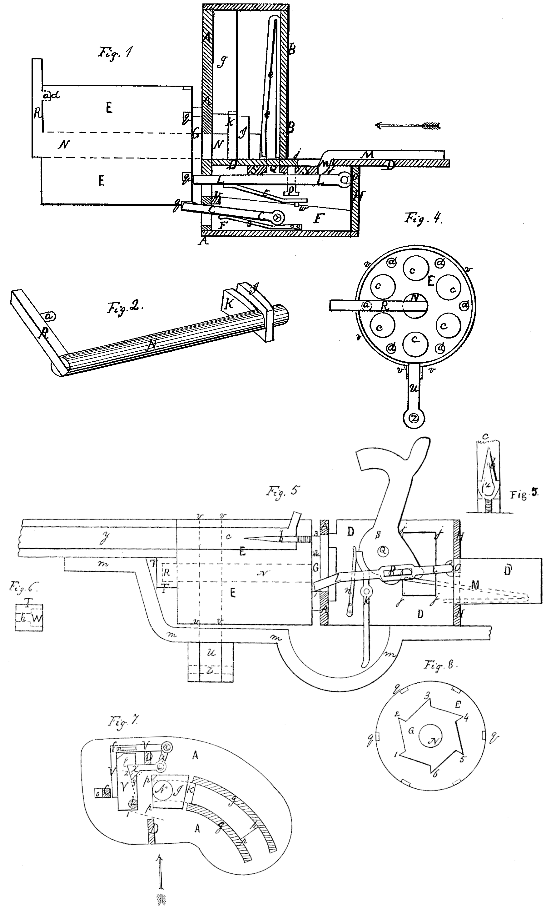
Fig. 1 is a top view of the lock and revolving cylinder. Fig. 5 is a view of the same from the left side, showing also part of the barrel, and one of the bars connecting the barrel and stock. Fig. 2 is a view of the mandrel on which the revolving cylinder turns. Fig. 4 is a view of the front end of the revolving cylinder and mandrel. Fig. 8 is a view of the back end of the same. Fig. 7 is a view of the back side of the front wall of the lock, showing the openings in this wall, the back end of the mandrel, and the levers by which the catch C is worked.
S, Figs. 5 and 1, is the cock of the gun, fastened to the middle wall, D, by its pivot-screw Q.
k is the trigger, also fastened to this wall by its pivot-screw, and n is the trigger-spring.
M, Figs. 1 and 5, is the mainspring, the back part of which is on the right side of the middle wall, D, but which, being turned in its course and passing through the opening j j j j, has its front end on the left side of this wall, as seen in Fig. 1.
The revolving cylinder E, in which the loads are placed, is turned on its axis (the mandrel N) in this manner: On the back end of this cylinder and concentric with its axis a plate, G, Figs. 8, 5, 1, and 7, is solidly fixed. This plate has steps 1 2 3, &c., cut around its edges, as shown in Figs. 8, 5, and 7, by operating on which the turning-lever L, Figs. 5 and 1, turns the cylinder. The back end of the turning lever L is fastened by a hinge-joint, O, Figs. 5. and 1, to one of the back walls, H, of the lock, so that its front end is at liberty to move both vertically and sidewise. Toward the middle of this lever is a slot (see Fig. 5) in which a long pin, P, Figs. 5 and 1, works. This pin is fastened into the lower part of the cock S, so that, as shown in Fig. 5, when the hammer of the cock descends to the tube the front end of the lever L will be raised, and when the hammer is drawn back again the front end of the lever L is forced downward. The lever L has a spring, t, Fig. 1, fastened to its left side, the back end of which works against an upright stud, w, which is fastened to the floor F. This spring presses the front end of the lever L always toward the right. The revolving cylinder E has notches q q, Figs, 8 and 1, cut at the proper points in its sides at its back end. Into these notches the catch C, Fig.1, is forced by its springs, (which constantly presses it to the right,) as each of the chambers c c, Fig. 4, comes into the proper position for firing. This catch is fastened by its pivot r, Fig. 1, to the floor F, and its front end passes through an opening, o, Fig. 7, in the front wall of the lock.
In Fig. 7 are seen the two bent levers X and V, by which the catch C is worked. The lever X is fastened by the pivot i, on which it turns, to the back part of the front wall, A, as shown in Fig. 7. The upper end of this lever is attached by the pivot x to the other lever, V; but they are not fastened to the wall at this point. In the lever V is a slot, as seen in Fig. 7, in which a pin, f, works, which pin is fastened to the back side of the front wall. Whenever the lower arm of the lever X is pressed downward the other lever, W, slides to the left “on the pin f, so that the catch C is then thrown to the left out of the notches q q, Figs. 1 and 7, made for it in the cylinder.
The mode in which the cylinder E is turned for each successive discharge and then held fast is this: The hammer of the cock S being up, as seen in Fig. 5, the front end of the turning-lever L is then at its lowest point, 1. (See Figs. 5, 7, and 8.) This lever passes through an opening, Y, Fig. 7, in the front Wall, A. As the hammer falls the front end of the lever L rises, and having passed from 1 to 2, Figs. 5, 7, and 8, along the left edge of the plate G, continues to pass up along the left edge of the horizontal arm of the lever X, Fig. 7, until it passes above its corner l. The spring t, Fig. 1, then throws the lever L to the right, so that it will be above the left end of the lever X, Fig. 7. Then, when the hammer of the cock is drawn backward, the front end of the lever L, Fig. 5, is forced down against the horizontal arm of the lever X, Fig. 7, which slides the other lever, W, and the catch C to the left, releasing the cylinder, as before described. After the front end of the lever L has carried down the lower arm of X for some distance it strikes the step 2, Figs. 7, 5, and 8, of the plate G, and pressing it also downward so turns the cylinder E to the proper position for firing a second time; but before the front end of the lever L completes its descent the left end of the lever X, Fig. 7, turning in a small circle, will leave its path, and then the spring s, Fig.1, will throw the catch C again toward the right, and the latter will be pressed into one of the notches q q., Figs. 1 and 8, cut for it in the cylinder E, as soon as the cylinder is turned far enough. After the levers X and V are released from the lever Lin its descent, Fig. 7, they will be thrown into their original position by the pressure of the catch C against them, the left arm of the lever X being prevented from rising above a horizontal position by that part of the middle wall, D, Figs. 7 and 5, immediately above it.
The advantages claimed for this lock are that it is stronger and less liable to get out of repair than the revolving locks now in use.
For convenience in loading the cylinder E can be moved out to one side, clear of the barrel, without detaching it from the gun. This is effected by the following means: The mandrel N—that is, the axis on which the cylinder E turns-is so arranged that it may be pushed backward by pressing back the cross-piece R, Figs, 1,2,4, and 5, fixed to its front end. On the back side of this cross-piece is a projection, a, which, when the mandrel is pushed back, enters one of the holes d d, Figs. 4 and 1, in the end of the cylinder E, so that the latter cannot turn.
At the back end of the mandrel N are two pieces, K and I, Figs. 1, 2, and 7. The front piece, K, when the mandrel is thrown forward, fits in the opening p p p p, Fig. 7, in the front wall, A. When the mandrel is pushed back the right end of this front piece slides between the two curved strips g g, Figs, 7 and 1, which are fastened edgewise against the back side of the front wall, above and below the opening p p p p, Fig. 7. The design of the other piece, I, which is broader than K, is to prevent the mandrel N from going forward beyond its proper position. The spring e, Fig. 1, is curved in the same manner as the opening pp. pp, Fig. 7, and is placed opposite to it on the back wall, B, Fig. 1. This spring presses the mandrel N constantly forward.
Around the front end of the cylinder E is a band v v, Figs. 4 and 5, in which the cylinder turns. Fastened to the bottom of this band is a radial arm, U, Figs. 4 and 5, which turns at its lower end on a pivot, Z, attached to strips descending from the bar m m which connects the barrel and stock. This bar is turned in its course around to the left of the radial arm U, so that the latter is at liberty to move out toward the right. Another bar, similar to m m, is to connect the barrel and stock on the upper side. When it is desired to move out the cylinder E to the right, so that it will be clear of the barrel y, Fig. 5, the mandrel N will be pushed back to the position shown in Fig. 1. The cylinder then may be pushed out to the right, the mandrel passing along in the opening p p p p, Fig. 7, in the front wall, A, and the front piece, K, Figs. 1, 2, and 7, passing between the curved strips g g, so that the mandrel cannot turn, while the piece I, Figs. 1, 2, and 7, holds the mandrel back to its proper position. By the means just described the mandrel N is prevented from turning, and the cylinder e also prevented from turning on the mandrel when they are thrown out to the right. The design of this is that the chambers c c, Fig. 4, maybe brought truly under the rammers, one for each chamber being fixed to a rammer-plate, so as to ram all of the charges at once. But as I do not apply for a patent for this mode of fixing the rammers and rammer-plate they are not particularly described.
Beneath the barrel y is a thimble T, Figs. 5 and 6, in which the front end of the mandrel N fits. The opening in the front part of it, h, Fig. 6, is just wide enough to allow the cross-piece R to enter it, so that the front end of the mandrel N cannot escape from it when the mandrel is thrown forward; but at the back end, W, Fig. 6, of the thimble the opening is wider, so that the mandrel can escape to the right when the latter has been pushed backward.
Into the bottom of each of the chambers c c c, Figs. 5, 3, and 4, of the cylinder E is screwed a needle-pointed cutter, b, of the shape shown in Figs. 5 and 3, the flat side of which is turned toward the cap-tube. In this cutter is an opening, at of the shape shown in Fig. 3, so that when the cartridge (which must be so made as to have but a single thickness of paper at its lower end) is rammed down till the paper strikes the shoulders (Fig. 3) of the cutter the powder will escape from the cartridge into the opening it, Fig. 3, and so connect with the tube. The object of this is to save the trouble of tearing the cartridge before loading.
The cutters may be made sharp, like a knife-blade, along their edges, or left rounded.
What I claim as my invention, and desire to secure by Letters Patent, is—
1. The arrangement of the turning-lever and the manner in which it is made to turn the revolving cylinder, and of the plate behind the cylinder, on which the turning-lever operates, substantially as described.
2. The arrangement and combination of the levers by which the catch that arrests the revolution of the cylinder is operated on, and the manner in which these levers are worked by the turning-lever, substantially as described.
3. The arrangement, substantially as de- a cutter, whether of the particular shape here scribed, by which the revolving cylinder is thrown out to the side so as to clear the barrel in loading without detaching the former from the gun.
4. The use of the cutter at the bottom of the bore of the barrel for opening the cartridges, substantially as described, and the use of such a cutter, whether of the particular shape herein described or not.
WM. HENRY MORRISON.
Witnesses:
J. B. Morrison,
A. F. Morrison.