
US 11470
ISAAC W. BROWN, OF WEST SPRING FIELD, MASSACHUSETTS,
FIRE-ARM.
Specification forming part of Letters Patent No. 11,470, dated August 8, 1854.
To all whom it may concern:
Be it known that I, Isaac W. Brown, of West Springfield, in the county of Hampden and State of Massachusetts, have invented certain new and useful Improvements in Fire-Arms; and I do hereby declare the following to be a full, clear, and exact description of the same, reference being had to the accompanying drawings, making a part thereof, in which—
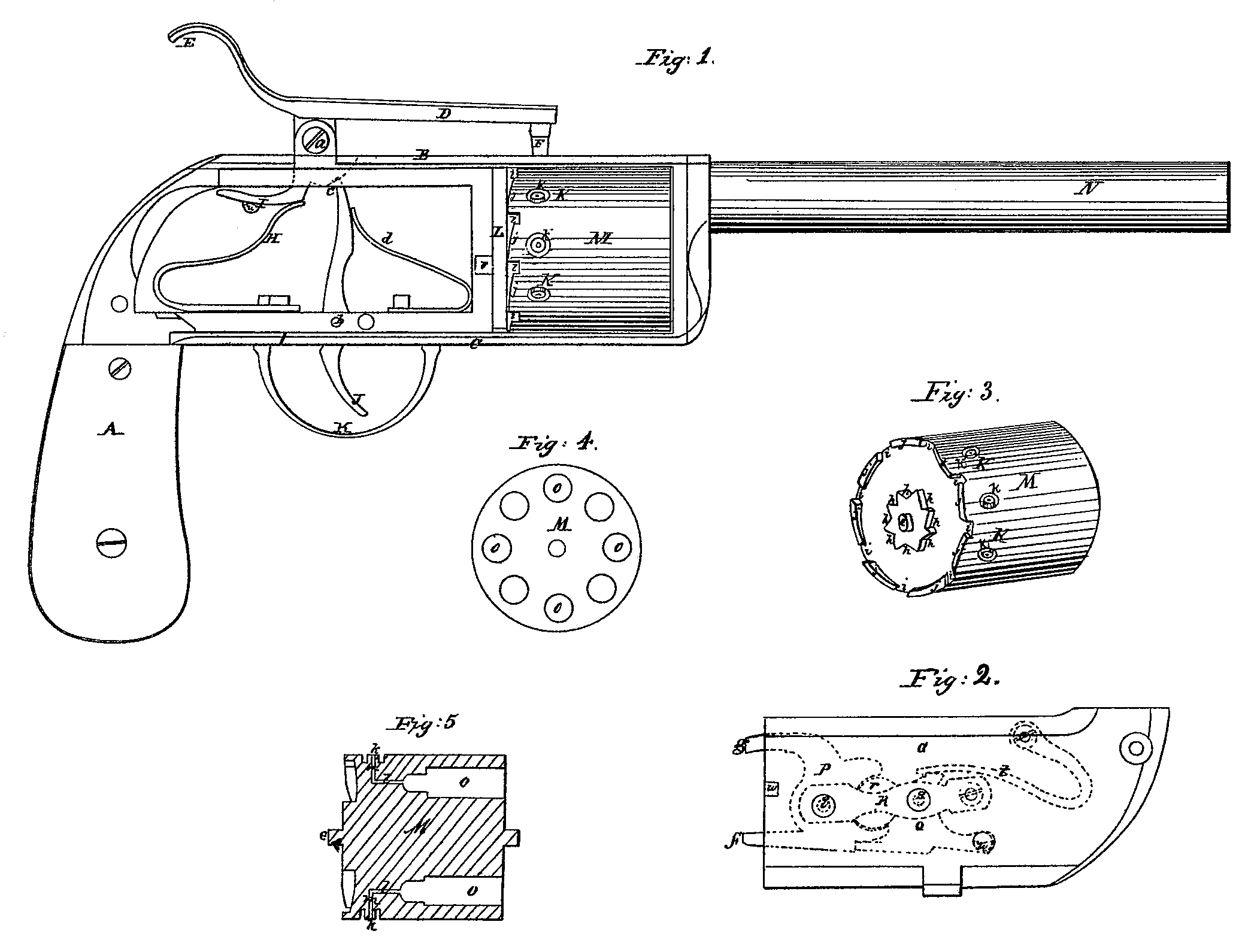
Figure 1 denotes a side view of the pistol with the side plate removed to represent the interior of the lock. Fig. 2 represents the side plate removed and turned over to represent the parts attached thereto which revolve the cylinder, the portions behind the side plate when in place being represented by red lines. Fig. 3 represents an isometrical view of the cylinder detached from the fire-arm. Fig. 4 represents a front end view of the cylinder, and Fig. 5 a vertical longitudinal section through said cylinder.
Similar letters where they occur denote like parts.
The nature of my invention consists in the giving of the cylinder a partial rotation by the cocking of the fire-arm, not sufficient, however, to bring the cap and its nipple entirely under the hammer, and completing the movement of the cylinder in the act of discharging the piece, so that the cap comes to its place just in time to meet the descent of the hammer, which explodes it.
To enable others skilled in the art to make and use my invention, I will proceed to describe the same with reference to the drawings.
A represents the stock of the fire-arm, and B the top and C the bottom plates, attached thereto and extending forward to form the frame upon which the several parts of the fire arm are arranged.
D is the hammer, pivoted at a, and E a lever or rear projection of the hammer for cocking it.
F is the right-angled projection on the hammer for striking against and exploding the cap. The face-plate G, Fig. 2, is removed to show the interior of the lock, in which lock E is the mainspring, resting against a bent lever, I, which is a part of the cock projecting through the top plate.
J is the trigger, pivoted at b. It extends upward so that its point c, as shown by dotted lines, shall catch into a recess cut in the under part of the hub of the hammer to hold it against the action of the mainspring H when cocked. A spring, d, presses against the top of the trigger, which holds the point of said trigger in such position as to insure its taking into the recess when the hammer is set or cocked.
K is the guard, which may be a spring and sprung into place in suitable holes or recesses, or it may be secured to the arm in any other well-known manner.
L is a plate or disk between the rear end of the cylinder M and the lock, in which plate one of journals e, Figs. 3, 5, rests and rotates, and through which plate suitable openings are made to allow the two toggle-levers f g, connected to the face-plate G, Fig. 3, to pass and to rotate the cylinder, as will be hereinafter described.
N is the barrel of the pistol.
In rear of the cylinder are formed eight recesses, i i i, &c., (the drawings representing a cylinder with eight chambers,) and around the rear journal eight cam-planes, h h h. The lever g, Fig. 2, moves over the curved planes j j, &c., between and into the recesses i i i, &c., as the cylinder is revolved, alternately moving and holding the cylinder. The lever f, Fig. 2, Works into the cam-planes h h, &c., completing the necessary portion of a revolution to bring the nipples k successively around under the hammer. The lever f operates in the act of cocking, bringing the nipple with its cap part of the way around, at which point the cap may be covered either by the top plate or a belt or ring, which should have a suitable hole through it, that the projection F on the hammer may reach the cap. When the trigger is pulled the cylinder is instantly rotated the balance of the required distance to bring the nipple in proper position to receive the blow of the hammer. Thus it may be said that the cylinder is rotated by two motions, the first in the act of cocking, the second in the act of discharging the arm.
The method of operating the levers f g will be hereinafter described.
The chambers O, as seen in Fig. 5, are recessed or offsetted near their bottoms, so as to form a chamber for the powder of less diameter than the chamber into which the bullet is placed. This is for the purpose of bringing the force of the powder more toward the center of the ball. From the rear of the recess or contracted chamber is bored a suitable hole, l, which extends just far enough back to meet a perpendicular hole, n, bored from the nipple down to it, this opening being for communicating the fire of the cap or priming to the rear of the powder in the chamber.
The nipples are cut out of the solid metal of the cylinder by countersinking around them to a sufficient depth to allow the cap to fairly set upon them, and so that said cap shall just be flush with the perimeter of the cylinder. The fire from the cap moves in a direct line from the point where the piece F strikes it until it reaches the opening at right angles to it from the bottom of the chamber.
The two levers f g are a part of a toggle plate, P, which is pivoted to the face-plate G at q, and in rear of this toggle-plate P is cut a rounded recess, into which a similarly-shaped head, r, formed on a toggle-plate, Q, which is pivoted at S to the face-plate, snugly fits. These two plates are secured in their places by the strap R, and against one of them, Q, a spring, t, operates to keep them in the position indicated in Fig. 2 after the piece I on the under side of the hammer or cock ceases to operate upon them, and to cause the after part or completion of the partial rotation of the cylinder. In rear of the toggle-plate. Q is a projecting arm, at, which, when the face-plate is in place, comes immediately underneath the piece I, Fig. 1, as shown at it in said figure. Now, by pressing down the lever E of the hammer the same motion through the piece I forces down the piece it on the plate Q, and through the toggle-joint formed by the two plates P Q it throws out or forward the lever f and draws in the lever g. As the lever f is thrown forward it catches against or into one of the teeth h and gives the cylinder a partial rotation, the lever g, which is drawn back by the same motion, releasing the cylinder for this purpose. When the trigger is pulled, which releases the parts operating these levers, the spring t, which was previously compressed, immediately throws up the two levers into the position shown in Fig.2, and the lever 9, in coming up, completes the rotation and locks the cylinder bypassing into one of the stops or openings i, the lever f slipping out and over the inclined side of the teeth, against which it next catches.
v is a wedge-shaped stud attached to the plate L, under which a Wedge-shaped recess, w, on the plate G slips to hold that end of the plate to the frame, the other end of the plate being held by a screw.
Having thus fully described the nature of my invention, what I claim therein as new, and desire to secure by Letters Patent, is—
Giving the cylinder a partial rotation by the cocking of the fire-arm and completing the movement necessary to bring the nipples successively under the hammer by the act of discharging the piece, substantially as described.
ISAAC. W. BROWN.
Witnesses:
M. P. Gritzner,
Saml. Grubb.