
US 517152
UNITED STATES PATENT OFFICE.
DANIEL B. WESSON, OF SPRINGFIELD, MASSACHUSETTS.
SWINGING CYLINDER AND TRIGGER-LOCK FOR REVOLVERS.
SPECIFICATION forming part of Letters Patent No. 517,152, dated March 27,1894.
Application filed December 7, 1893. Serial No, 492,964. (No model.)
To all whom it may concern:
Be it known that I, DANIEL B. WESSON, a citizen of the United States, residing at Springfield, in the county of Hampden and State of Massachusetts, have invented new and useful Improvements in Revolving Firearms, of which the following is a specification.
This invention relates to revolving fire-arms and more particularly to revolver pistols in which the cylinder thereof is supported on a swinging yoke-frame which has its support in the frame of the arm and whereby said cylinder is adapted to be swung to one side of the last-named frame, and so far outside of it, as to permit of ejecting cartridge shells therefrom and for reloading the cylinder; and the invention consists in certain details of construction in pistols of this class all as hereinafter fully described and more particularly pointed out in the claims.
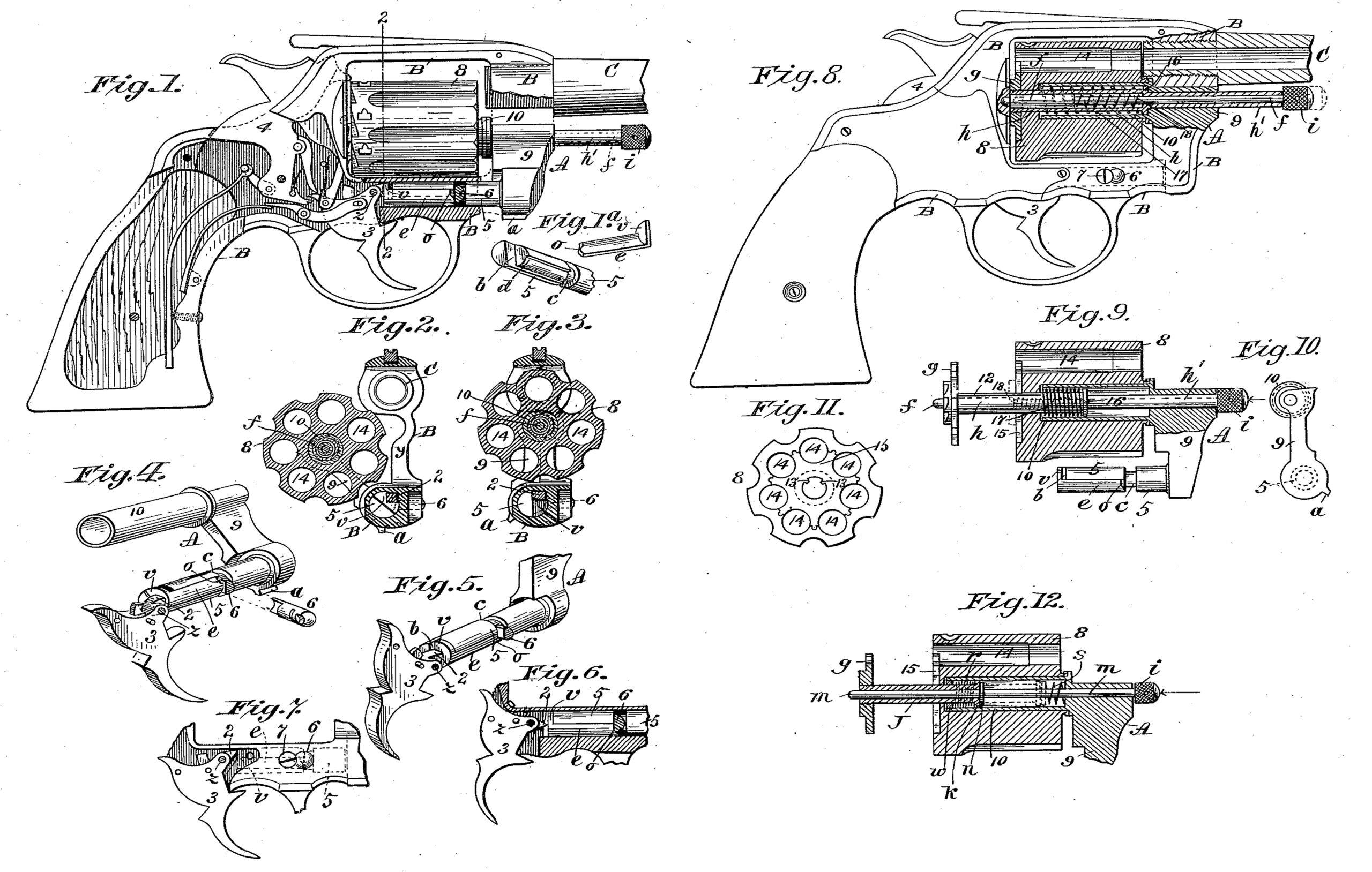
In the drawings forming part of this specification, Figure 1 is a side elevation, partly in section, of a revolving fire-arm embodying my improvements, the barrel thereof being shown broken off, and the cylinder in about the outwardly swung position illustrated in Fig.2. Fig.1a is a perspective view of parts hereinafter described. Figs. 2 and 3 are sectional views from the rear on line 2—2, Fig.1; Fig. 2 showing partly in full, and partly in dotted lines, the form of that part of the cylinder-yoke intermediate of its two arms, and the cylinder swung out of the pistol-frame, and Fig. 3 showing the cylinder within said frame. Fig.4 is a perspective view of the yoke on which the cylinder is supported, and of the trigger which is shown in this figure in the position opposite the extremity of the lower arm of said yoke which it must assume when the cylinder is not in firing position, this figure also showing a combined yoke-locking and cam-pin by which the cylinder yoke is retained in position in the frame of the arm and by which, a movable part on said arm is actuated; this figure showing a section of the inner end of said pin in operative position in an annular groove around said lower arm. Fig. 5 is a perspective view of a portion of said yoke and the lower arm thereof, and of the trigger at the extremity of said arm. A section of said retaining pin is shown in this figure in engagement with the annular groove around said arm and in its relation to the aforesaid movable part thereon. Fig. 6 is a longitudinal, sectional view of that part of the frame of the arm in which the trigger is hung and a side elevation of the extremity of the lower arm of the cylinder-yoke, shown therein, and a side elevation of the trigger. A section of the said retaining pin is shown in connection with said yoke-arm. Fig. 7 is a side elevation of that part of the frame of the arm extending beneath the cylinder thereof; this figure showing the trigger in side elevation uncovered and hung to said frame part and the said locking and cam-pin in end elevation in said frame part and its retaining screw. In this figure the position of the lower arm of the cylinder-yoke within the said part of the frame of the arm is indicated in dotted lines. Fig. 8 is a side elevation of the revolving fire-arm partly in section, the barrel thereof being shown broken off. This figure illustrates certain improvements in mechanism for operating the cartridge shell ejector combined with the cylinder retaining piston whereby the cylinder is secured in firing position in the arm. Fig. 9 is a similar view of the cylinder of the arm and of the ejector devices shown in Fig. 8, but showing the latter in different position and showing the lower portion of the cylinder yoke in side elevation and its upper portion in longitudinal section, the upper arm of said yoke being shown in position within said cylinder. Fig. 10 is a front end elevation of the cylinder yoke and of the arm, 10, thereon. Fig. 11 is an elevation of the rear end of the cylinder. Fig. 12 illustrates a modification of the construction of the ejector devices shown in Figs. 8 and 9.
The particular improvements in revolvers herein shown and described relate to an improved construction of safety devices which so act as to prevent the arm from being fired unless the cylinder is in proper firing position in front of. the recoil plate thereof; and to an improved construction of the cylinder yoke-frame, the cylinder-pin, and the ejector operating devices.
In the drawings, in Fig. 1 thereof, are shown in side elevation, the hammer, 4, the trigger 3, and the usual intermediate mechanism in an arm of this class which is known as a self- cocking revolver. The said trigger is constructed with a forwardly extending projection, 2, more distinctly illustrated in Figs. 4 to 7, inclusive, extending toward the rear end of the lower arm, 5, of the cylinder yoke-frame, A. The general frame of the arm is indicated by B, and the barrel by C. The trigger, 3, is pivoted to said frame, B, at z, and that portion of the latter-named frame, which extends forwardly from where the trigger is pivoted, and under the cylinder, is perforated longitudinally as shown in Figs. 1, 2, 3, and 6, said perforation being also indicated by dotted lines in Figs. 7 and 8. The said longitudinally perforated portion of the frame, B, is perforated transversely of its length to permit of fixing therein a pin, 6, by means of a screw, 7, therebeside, as shown in Fig. 8 and elsewhere, and is united with that portion of the same frame which extends over the cylinder, 8, of the arm by that part of said frame which is indicated by y, Fig. 2, this latternamed part being broken away in Fig. 1 to better show a part of the cylinder yoke-frame below described. The part, 9, of the yoke-frame, A, is made to conform in shape to that of one side of the said part, y, of the main frame, B, so, that when the cylinder, 8, is swung to the position shown in Figs. 3 and 8, or to a firing one, the united parts, 9 and y, present a proper front end-view of the frame part of the pistol under the barrel. A stop-projection, a, is made on the yoke-frame part, 9, which engages with the part, y, of the main frame, B, when the cylinder is swung outwardly, as in Fig. 2, to limit said swinging motion. The said cylinder yoke-frame, A, consists of a tubular arm, 10, the said lower arm, 5, and an intermediate yokepiece, 9, to which said arms, 5 and 10, are rigidly fixed by one end as shown in Fig.4. The upper tubular arm, 10, of the cylinder yoke-frame serves the purpose of the part in revolvers which is ordinarily termed the base-pin, for upon said arm, 10, the cylinder revolves and is supported. The lower arm, 5, of said yoke-frame extends from its junction with the part, 9, thereof a certain distance, as shown in Figs. 4 and 5, of plain cylindrical form and has an annular groove, c, formed therein. The extremity of said arm, 5, is of half-round form in end-view, as clearly shown in Fig. 1a, leaving on said arm an offset, b. From said annular groove, c, around said arm to said offset, a longitudinal groove, d, is formed which is adapted to receive the shank of a safety-slide, e, which shank is of a circular form in cross section corresponding with the cylindrical plane of the part of the arm, 5, on which it is placed. The end of said slide, whose operative position is at the border of, or slightly within, said annular groove, c, as shown in Figs. 4, 5, and 6, is made of cam-shape, as shown at o, Fig. 1a, and its inner surface has a form corresponding to the circularly formed base of said groove, d. The said slide, e, has a fixed head, v, thereon which has externally substantially the same superficial area as the said half-round end of the arm, 5. The said slide, by means hereinafter described, is given a longitudinal movement on the yoke-arm, 5, which movement is induced by the aforesaid swinging movement of the cylinder, 8, and said head is thus moved on said offset, b, toward and from said half-round end of said arm, 5, and at times according to the position of the cylinder, 8, rests fixedly flush with the said half-round extremity of arm, 5, as shown in Fig. 4, or in a position back of, or retired from, said extremity, as shown in Fig. 5. The said movement of the safety-slide, e, whereby the head, v, is brought to the end of arm, 5, is effected when said arm is given a rolling motion by the outwardly swinging movement of the cylinder, 8, by the engagement of the cam-shaped end, o, of the slide with the end of said pin, 6, which is secured in the frame of the arm and projects into the said annular groove, c, in the arm, 5. Said pin, while thus serving by its projection into said annular groove, c, to attach the said yoke-frame to the arm, also serves as a fixed abutment on the arm frame against which the end of said slide moves and is thereby caused to have a sliding movement on said arm, 5. The position of the cylinder, 8, when the head, v, is brought to said flush position, shown in Fig. 4, is that illustrated in Fig. 2, or swung outwardly from the frame of the arm for the purpose of ejecting shells and reloading the cylinder and the engagement of the inner end of the slide, e, with the pin, 6, is such that the said slide is prevented from taking the retired position shown in Fig.5 until the cylinder shall have been brought to a complete firing position within the frame of the arm, as shown in Fig. 8, and the cylinder-yoke arm, 5, shall have been rolled from the position shown in Fig. 4 to that shown in Fig. 5 by said movement of the cylinder, thereby so changing the relative position of the cam-end of, the slide to the pin, 6, that the slide is free to recede on the arm, 5, and permit its head, v, to occupy the position shown in Fig. 5.
The purpose of the above described construction and operation of the arm, 5, of the cylinder-yoke, A, and of the safety-slide thereon is to provide a part on said arm opposite the trigger which shall have a movement toward and from the latter, as described, and which, when moved toward the trigger, shall be there so rigidly held and in such proximity to an adjoining part of the trigger that the latter can not be operated to fire the arm while the cylinder thereon is not in firing position before the hammer.
For the purposes of this invention, the trigger is constructed with the aforesaid forwardly projecting portion, 2, or having such form on that part of it that such engagement with the head of the safety-slide as is above described is insured. Thus it will be clearly understood that when the cylinder occupies the firing position shown in Fig. 3 thereby bringing the yoke-arm, 5, to the position shown in Fig. 5, the trigger may swing freely forward when pulled for firing impinging against the head of the safety-slide; e, and moving it freely on the arm, 5; but that when the cylinder is swung laterally out of a firing position, like, or similar to that shown in Fig. 2 and thereby rolling the yoke-arm, 5, and the safety-slide, e, to the positions shown in Fig. 4, the head of the safety-slide is rigidly held so near to the adjoining part of the trigger, that the latter cannot be pulled to fire the arm, and hence provision is thus made against the possibility of discharging the arm or exploding any cartridge in the cylinder when the latter is not in its proper position behind the barrel.
Fig. 4 illustrates the normal position of the. trigger when the hammer is not cocked, and Fig. 5 the position of the trigger when drawn back to self-cock the hammer and fire the arm.
As aforesaid, the tubular arm, 10, of the yoke-frame, A, constitutes the cylinder support of the pistol, or “ base-pin,” as ordinarily called, and the cylinder is suitably bored from its forward end rearwardly partly through the same, of suitable diameter to receive said arm, as clearly shown in Figs.8, 9, and 12, and from the base of said perforation which receives the arm, 10, a perforation of reduced diameter is made, through which the rear end of the ejector-piston, A, passes.
Referring now to the ejector construction illustrated in Figs. 8 and 9, the tubular ejector-piston; h, is located within said tubular arm, 10, and extends from thence through and projects beyond the rear end of the cylinder, and the ejector spider, g, is secured thereto, preferably by screwing it thereon. The said piston, h, has a tubular extension, h’, of reduced diameter passing through the part, 9, of the yoke-frame, A. The cylinder-locking pin, f, occupies a position within said ejector-piston, as. shown in Fig. 8,—one end extending forwardly through the extension, h’, of said piston, and has fixed thereon the knurled. finger-piece, i. Said ejector piston is provided with one or more longitudinal grooves, 12, (Fig. 9) with which projecting bosses, 13, of the cylinder engage so that the said ejector devices and the cylinder shall turn together. The spider, g, is preferably made of such form as will fit.the depressed conformation, 15, indicated in Fig. 11 between the cartridge chambers, 14, of the cylinder, 8. That part of the said cylinder-locking pin, which projects to the rearward of the spider, g, as shown, enters a centrally located socket in the recoil plate of the arm, thereby locking the cylinder in firing position in the frame of the pistol, when it is swung upwardly to the position shown in Fig. 8. That part of the said ejector piston, h, which is within the arm, 10, has an annular shoulder, 16, thereon, (see Fig. 9) and from said shoulder to its rear extremity it is of uniform diameter. Upon said last-named part of said piston a coil spring, 17, is placed, one end of which abuts against said shoulder, 16, and its opposite end against that part of the cylinder, 8, at the rear end of the tubular arm, 10. Said spring serves to retain said piston and the spider, g, normally in the position in which they are shown in Fig. 8. At the inner end of said larger portion of the cylinder-locking pin, f, (which is within the ejector-piston, h,) is another shoulder, and a spiral spring, 18, is placed on said pin, f, one end of which abuts against said last-named shoulder, and the opposite end
bears against the base of the tubular part of the piston, h, which is within said arm, 10; thus spring, 18, acts to force the pin, f, rearwardly and hold its rear extremity normally in said socket in the recoil plate of the arm. When the pin, f, is so held, the said finger- piece, i, bears against the forward end of the part, h’, of the piston, h, as shown in Fig. 8.
The above described improvements appertaining to the manipulation of the cylinder, 8, in swinging it laterally out of, and back into, the frame of the arm; and to the described ejector-devices, have a more or less conjoint action, and their operation is as follows: To release the cylinder and swing it laterally, the finger piece, i, is grasped and the locking-pin, f, is drawn forward out of its socket in the recoil plate. The cylinder is then brought to the position illustrated in Fig. 2. Upon releasing the pin, f, spring, 18, returns it to its said normal position. The operator then presses upon the end of the said piece, i, moving the ejector-piston, h, and ejector, g, rearwardly, as illustrated in Fig. 9, and thereby ejecting such shells as may be in the cylinder. Upon releasing the said ejector piston, spring 17 acts to return the said ejector parts to their normal positions, as in Fig. 8. After loading the cylinder with cartridges it is pushed into place in the frame of the arm, and the pin, f, by the engagement of its extremity with the surface of the recoil plate, is caused to. withdraw slightly into the cylinder, but when brought opposite said socket therein, the spring, 18, acts to drive its rearward end thereinto, thus automatically locking the cylinder in its firing position.
The modified construction of the ejector devices and cylinder-locking-pin illustrated in Fig. 12, maybe substituted for those above described, if desired, but it involves the use of springs for actuating the locking-pin and retiring the ejector devices, which are not so certain of action as are those constructed and arranged as in Figs. 8 and 9. In Fig. 12 the locking-pip, m, has a shoulder, n, thereon, which bears against a spring, s, and the latter forces said pin into said socket in the recoil plate. The arm, 10, has a ring-nut, w, in its open end through which the ejector-piston, J, moves, which forms an abutment for one end of a spring, r, which (though shown compressed in said last-named figure) acts against a shoulder, k, on said piston to move the latter and the pin, m, into the cylinder. The said shoulder, k, impinges against said shoulder, n, on the locking-pin, m. The manipulation of the parts in said modified construction is substantially the same as that described relative to the construction shown in Fig. 8.
Having thus described my invention, what I claim, and desire to secure by Letters Patent, is—
1. The combination with the cylinder of a revolving fire-arm, of a yoke frame having an arm on which said cylinder is supported and a second arm supported in the frame of the fire-arm and extending near the trigger thereof, a safety piece in proximity to said second arm and having movement therewith, toward and from said trigger, and an abutment in the frame against which said safety piece is borne and thereby moved, all substantially described.
2. The combination with the cylinder of a revolving fire-arm, of a yoke-frame having an arm on which said cylinder is supported, and a second arm supported in the frame of the fire-arm and terminating near the trigger thereof, and having a rolling motion induced by the movement of said cylinder laterally, a safety-slide. having a shank with a cam-shaped extremity and a head on its opposite end in proximity to the end of said second arm, said slide having a longitudinal movement on said last-named arm toward and from the trigger of the arm, and a fixed abutment in the frame of the fire-arm against which said cam-shaped end of said slide impinges and whereby it is moved, substantially as described.
3. In a revolving fire-arm, the cylinder of which is movable laterally, a yoke-frame having an arm on which said cylinder is supported, and a second arm supported in the frame of the fire-arm and terminating near the trigger thereof and having a rolling motion induced by the movement of said cylinder laterally, a safety-slide having a shank with a cam-shaped extremity and a head on its opposite end in proximity to the end of said second arm, said slide having a longitudinal movement on said last-named arm toward and from the trigger of the arm, a fixed abutment in the frame of the fire-arm against which said cam-shaped end of said slide impinges to be moved thereby in one direction, combined with the trigger located opposite the head of said slide and in engaging proximity thereto, substantially as set forth.
4. A yoke-frame for a revolving fire-arm having an arm on which the cylinder is supported, and a second arm entering, and having a rolling motion in the frame of the arm under the said cylinder, and having an annular groove therein, and a longitudinal groove extending from said annular groove to the extremity of the arm, combined with a safety-slide having a shank engaging in said longitudinal groove having a cam-shaped end and a head on its opposite end in proximity to the trigger, and a fixed abutment in the frame of the fire-arm engaging in said annular groove, and with which the cam-shaped extremity of said slide engages to be actuated thereby, substantially as set forth.
5. In a revolving fire-arm, the cylinder of which is movable laterally, a yoke-frame having an arm on which said cylinder is supported, and a second arm supported in the frame of the fire-arm and terminating near the trigger thereof and having a rolling motion induced by the movement of said cylinder laterally, an annular groove surrounding the same, and an offset thereon producing an extremity of half-round form, a fixed abutment in the frame of the arm engaging in said annular groove, a safety-slide having a shank with a cam-shaped extremity engaging with said abutment, and a head on its opposite end of semi-disk-form in proximity to the end of said second arm, said slide having a longitudinal movement on said last-named arm, induced by thé said rolling movement of said arm, whereby the head of said slide is given a movement on said half-round portion of said second arm toward the extremity thereof, combined with the trigger located opposite the head of said slide and in engaging proximity thereto, substantially as set forth.
6. In revolving fire-arms, the cylinder of which is movable laterally, a yoke-frame having a tubular arm on which said cylinder rotates, the combination with said frame and arm, of a tubular ejector-piston within said tubular arm extending through the rear end of the cylinder and forwardly through said yoke-frame, and having the extractor-spider thereon and a spring engaging therewith and with the interior of the cylinder described acting to move said spider against the end of said cylinder, a cylinder-locking-pin within said piston and projecting beyond its forward extremity and rearwardly through said spider and a spring thereon acting to move said locking-pin against the recoil-plate of the arm and engage it therewith, substantially as set forth.
7. The combination with the cylinder of a revolving fire-arm and the yoke-frame therefor on, which it swings laterally, of an ejector-piston carrying a cartridge ejecting spider on one end, and a centrally located cylinder-locking pin having a longitudinal movement within said piston, substantially as set forth.
8. In a revolving fire-arm, the cylinder, the side swinging yoke supported in the frame and supporting said cylinder, the trigger, and a separate safety piece in the frame in position to be actuated by said yoke, and to act as a trigger stop when the cylinder is in unsafe position, all combined substantially as described.
DANIEL B. WESSON.
Witnesses:
H. A, CHAPIN,
WM. S. BELLOWS.