
US 520468
UNITED STATES PATENT OFFICE.
DANIEL B. WESSON, OF SPRINGFIELD, MASSACHUSETTS.
REVOLVER-LOCK MECHANISM.
SPECIFICATION forming part of Letters Patent No. 520,468, dated May 29,1894.
Application fled January 26, 1894. Serial No, 498,132. (No model.)
To all whom it may concern:
Be it known that I, DANIEL B. WESSON, a citizen of the United States, residing at Springfield, in the county of Hampden and State of Massachusetts, have invented new and useful Improvements in Revolving Firearms, of which the following is a specification.
This invention relates to fire-arms and particularly to improvements in revolvers having reference to various details of construction thereof, all as hereinafter fully described and more particularly pointed out in the claims.
The object of this invention is to improve revolving fire-arms, in various particulars.
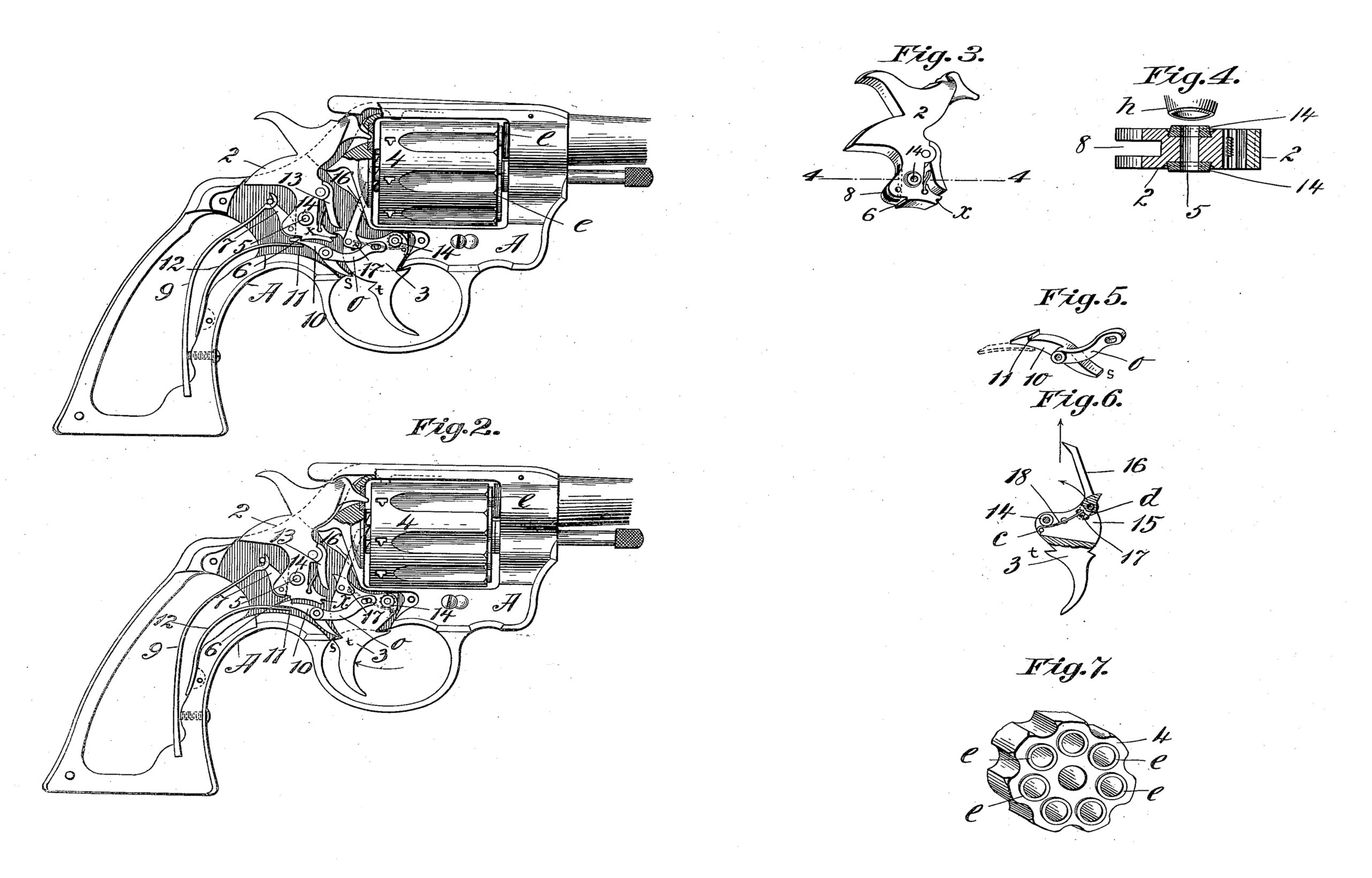
In the drawings forming part of this specification, Figures 1 and 2 are side elevations of a revolving fire-arm embodying my improvements, said figures showing the side plate of the arm removed and the extremity of the barrel broken off, Fig. 1 illustrating the normal position of the lock mechanism after the discharge of the arm, and Fig. 2 illustrating the position of said mechanism when the hammer strikes a cartridge to explode it. Fig. 3 is a perspective view of the hammer of the arm, and Fig. 4 is an enlarged sectional view of the lower. portion of the hammer on line 4—4, Fig. 3, and of the end of a swaging tool, the use of which is hereinafter described. Fig. 5 is a perspective view of a part of the locking mechanism hereinafter described, said figure showing in dotted lines the position of the end of a spring acting in said mechanism. Fig. 6 is a side elevation, partly in section, of the trigger the cylinder-moving arm connected therewith and a spring in the trigger having an engagement with said arm. Fig. 7 is a perspective view of the end of the cylinder of the weapon adjoining the rear end of the barrel.
In the drawings, A indicates the frame of the arm; 2, the hammer; 3, the trigger; and 4, the cylinder.
In the construction of rebounding lock mechanism for arms of the class herein shown and described and other analogous ones, as heretofore practiced, no means have usually been provided for preventing the accidental movement of the hammer against a cartridge acting.after the hammer shall have rebounded, whereby the hammer is rigidly retained in a retired position relative to any cartridge which may move in front of it, until the trigger shall have been again operated to fire the arm. The absence of such provision for retaining the hammer in said retired position leaves the latter dependent upon some spring action to hold it away from a cartridge, and, consequently, a force inadvertently exerted against the hammer capable of overcoming said spring action might drive the hammer against a cartridge and produce an accidental discharge of the arm. To provide against the danger of such accidental discharge of the arm and to surely and rigidly maintain the hammer thereof in what may be termed a “safety-position,” the below described improved hammer locking or retaining mechanism is provided.
The hammer, 2, is pivoted in the usual manner at 5 in the arm and in its lower end is formed a catch-notch, 6. A stirrup, 7, is pivoted in a slot, or recess, 8, (see Fig. 3,) in the rear edge of the hammer, and that part of the stirrup below its pivot point, as shown in Figs. 1 and 2, is made to engage with the base of said slot below said pivot, whereby the free end of said stirrup while engaged with the main spring, 9, can have no swinging movement any farther away from the rear edge of the hammer than it is brought to by the action of said spring and has, consequently, when so connected, such rigid engagement with the hammer that the extreme forward movement of the latter, as illustrated in Fig. 2, which is required for striking a cartridge in the cylinder, 4, causes the end of the stirrup which is in engagement with the main spring, 9, to move upward near the extremity of said spring, as illustrated in said last named figure, when the hammer so strikes a cartridge. The immediate reaction of said spring against the stirrup causes the upper extremity of the hammer to be instantly retired rearwardly away from the cylinder, as illustrated in Fig. 1, and the extremity of the stirrup to take its normal position relative to said spring there shown. This last described action of the hammer is what is termed the rebound thereof, but were there nothing to prevent it it will be clearly understood that a blow upon the rear edge of the hammer, while held in the position shown in Fig. 1, by the action of the main spring, only, the hammer may be driven forwardly against a cartridge in the cylinder by some blow thereon with sufficient force to explode a cartridge, accidentally. To provide against said accidental movement of the rebounding hammer a catch-lever, 10, is pivoted below the latter having a catch-notch, 1, thereon which is adapted to automatically engage with the said notch, 6, on the lower end of the hammer, when the latter shall have been, by said reaction of the main spring, 9, brought to the rearward position shown in Fig. 1. A spring, 12, acts under said lever to so engage it.
Fig. 2 shows the forward position of the hammer when it strikes the end of a cartridge and it also illustrates the position of said catch-lever relative to the notch, 6, in the hammer at that time. The last named figure shows the trigger, 3, in the position in which it is held when the arm is discharged. Said catch-lever, 10, has a second arm, o, through which is a slot, as shown, near its extremity, and a pin in the side of the trigger engages in said slot. The engagement of the trigger and the catch-lever, 10, thus effected, has for its end the movement of the catch notch, 11, away from the notch, 6, on the hammer in the act of firing the arm, so that the hammer may be free to strike the cartridge. The catch-lever 10 also has a third arm s, which acts as an abutment, against which the shoulder t of the trigger is stopped when the trigger has reached its extreme movement.
By reference to Fig. 2, it is seen (as above set forth) that when the cartridge is so struck, the notch, 6, on the hammer may be slightly back of the notch, 11, in the lever, 10, but the said rebound of the hammer brings it, relatively to said notch in lever, 10, to the position shown in Fig. 2, so that said notches, 6 and 11, are in coinciding positions, and will co-engage as in Fig. 1; when the trigger is released and swings to the position shown in the last-named figure. The spring, 12, has one end engaging under the end of lever, 10, to move the latter against the hammer, and said spring serves, by its connection with the trigger through said lever, 10, and the arm, o, thereof, also a8 a trigger spring to swing it from the position shown in Fig. 2, to that shown in Fig. 1, when the catch of lever 10, is engaged with the notch, 6, of the hammer.
The lock mechanism of the arm herein described adapts the latter to be used either as a self-cocking-pistol (cocking by pulling the trigger), or to be cocked by using the thumb as in ordinary arms. When the pistol is to be fired by self-cocking the rear point of the trigger, 3, and the trip-lever, 13, on the front edge of the hammer occupy the positions shown in Fig. 1 whereby, when the trigger is pulled, it engages with the under side of said trip lever and thereby the hammer is swung back to full cock. The end of the trigger then swings clear of the extremity of the trip-lever, as shown in Fig. 2, letting the hammer swing forward and strike the cartridge, and then, upon releasing the trigger the latter swings down past the free end of said trip lever, the latter swinging back to let the point of the trigger pass to the position shown in Fig. 1. A spring, shown back of said trip lever, operates to retain it in the position shown in Fig. 1 when not interfered with by the trigger,as aforesaid. When the arm is fired by cocking, by hand, the thumb is applied in the usual way to the hammer and as the hammer moves over, backwardly, it engages under the point of the trigger until the latter shall drop into the notch, 7, in the hammer and then the latter is at full cock. The operation of the catch-lever, 10, as above described, is the same whether the arm be fired as a self-cocking one, or otherwise.
The hammer, 2, and the trigger, 3, each, has rigidly fixed in the opposite sides thereof and
surrounding their pivot bearing, the bushings, 14 (see Fig. 4 which illustrates in enlarged view a section of the hammer on line 4—4, Fig. 3 and clearly illustrates the position of said bushings at each end of the pivot bearing, the bushing construction being identical both in the hammer and in the trigger). The said bushings are preferably hardened before being inserted in the sides of the trigger or hammer and they project beyond the surrounding plane of the sides of said parts and thus provide against the consequences of the excessive wear of said bearings and by reason of their projecting positions beyond the sides of the parts, as aforesaid, they prevent the contact of the side plates of the arm with the sides of the hammer and trigger, thereby leaving the latter greater freedom of motion. Countersunk recesses are formed in the sides of the hammer and trigger to receive the said bushings which bushings are of circular form and of conical shape, exteriorly, and the bushings are secured in said recesses by forcing the end of a hollow tool, h, (see Fig. 4) against those portions of the sides of the hammer or trigger immediately surrounding said recesses, thereby swaging the last named parts forcibly against the tapered bushings and rigidly fixing them in their places.
The cylinder turning arm, 16, which is pivotally connected by one end to the trigger and
has its free end passing through a slot in the recoil plate and engaging with the ratchet teeth on the rear end of the cylinder, 4, to turn the latter, is given the requisite endwise movement through the swinging motion of the trigger when it is operated to fire the arm. Heretofore the requisite spring which has been applied to move the free end of said arm, 18, against the end of the cylinder and there to retain it in operative relation to said ratchet teeth, has been applied outside of the trigger. That arrangement of said spring is inconvenient for the reason that there is usually a lack of sufficient room to so apply it that it can act with proper freedom and without interference from other parts of the lock mechanism. To avoid the said inconveniences as to said spring location the trigger in the construction herein shown and described has formed therein (see Fig. 6) a chamber, 15, to receive the arm-spring, 18. The form of said arm, 16, on the outside of the trigger is shown in Figs. 1 and 2 and under that part of the arm near its pivotal connection with the trigger is formed a curved opening, d, in the side of the trigger, and a pin, 17, is fixed in said arm which passes through said slot and projects more or less into said chamber in the trigger. The spring, 18, is secured by one end in said chamber in the trigger as shown in Fig. 6, and passing under the pivot-bearing of the trigger has its free end bearing upon the said pin, 17, in the arm, 16, and the action of said spring causes the said arm to swing in the direction indicated by the curved arrow in the last named figure, while, when the trigger is pulled, the arm moves against the ratchet on the cylinder of the arm in the direction of the straight arrow in said figure.
Revolver cylinders have usually been made with plane surfaces at the end of the cylinder which adjoins the barrel. An exception to this has been a cylinder with sharp edged rings at its front, around the chambers, which rings were forced into the barrel by crowding the cylinder forward before firing. I form the front of the cylinder 4 with annular projections e on its front, as shown in Fig. 7. This leaves a space or recess between these rings for the reception of the products of combustion, while the rings themselves present narrow contact faces against the end of the barrel, and these faces are scraped clean by the rotation of the cylinder, insuring a close joint and easy operation. The rings may be milled on the cylinder, or may be projecting bushings.
What I claim as my invention is—
1. The combination, in a fire-arm, of the hammer, the stirrup pivoted thereto and having aside bearing against the hammer to limit its movement around the pivot, and the main spring having an inclined surface engaging said stirrup, and acting to rebound the hammer by the movement of the engaging part of the stirrup along said incline, and the hooked lever pivoted in the frame and engaging the hammer to prevent its fall after the rebound, all substantially, as described.
2. A pivoted part of a gun lock having a recess in the side of its body, surrounding the bearing opening, and a perforated frustoconical disk secured in said recess by the metal of the body upset about the disk, substantially as described.
3. In a revolving fire-arm, the frame, the barrel projecting slightly inside the cylinder recess in said frame, and the cylinder in said recess, having a rigid support against forward movement, and having projecting rings surrounding the cartridge chambers, extending forward from the body of the cylinder, all combined substantially as described.
DANIEL B. WESSON.
Witnesses:
H. A. CHAPIN;
WM. S. BELLOWS.