
US 51985
UNITED STATES PATENT OFFICE.
ELI WHITNEY, OF NEW HAVEN, CONNECTICUT.
IMPROVEMENT IN REVOLVING FIRE-ARMS.
Specification forming part of Letters Patent No. 51,985, dated January 9, 1866.
To all whom it may concern:
Be it known that I, Eli Whitney, of New Haven, county of New Haven, and State of Connecticut, have invented a new and Improved Repeating Fire-Arm; and I do hereby declare that the following is a full, clear, and exact description thereof, reference being had to the accompanying drawings, making a part of this specification, in which—
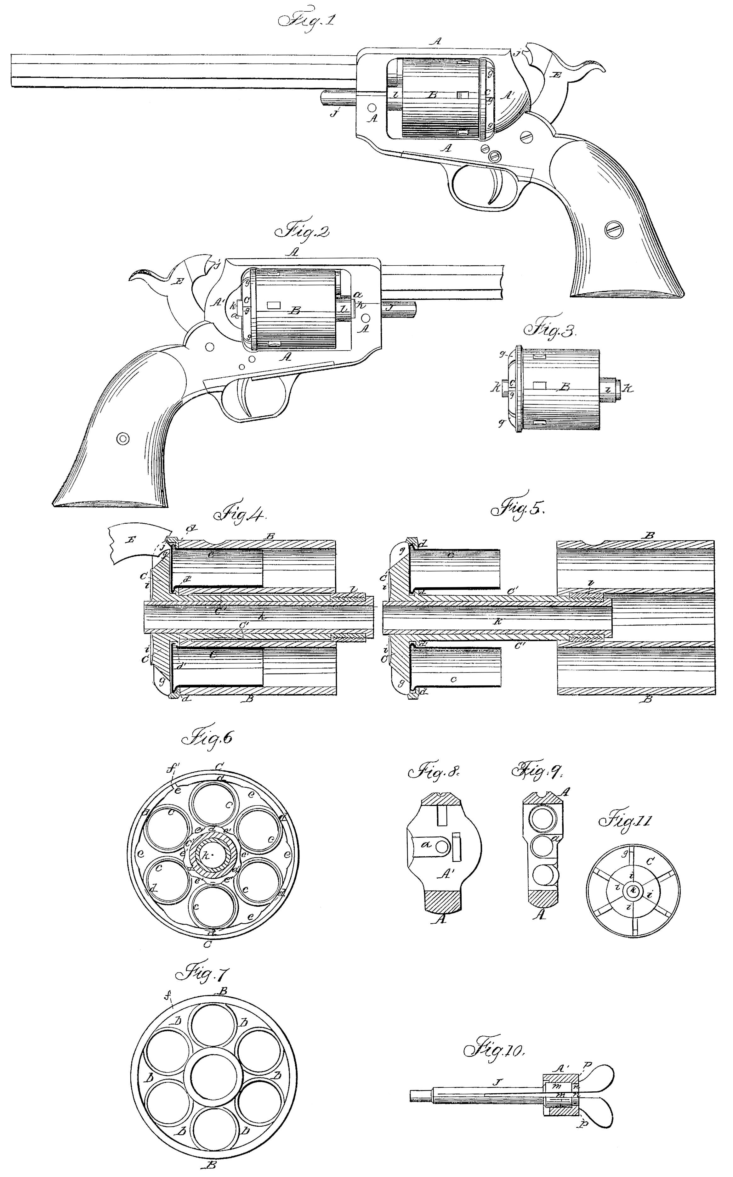
Figure I is a side view of a repeating-pistol having my invention applied to it. Fig. 2 is a view of the opposite side of the pistol. Fig. 3 is a side view of the revolving cylinder. Fig. 4 is an enlarged diametrical section through the revolving cylinder and recoil-shield. Fig. 5 is a similar view, showing the recoil-shield partially withdrawn from the cylinder. Fig. 6 is a front-end view of the recoil-shield, Fig. 7 is a view of the breech end of the revolving cylinder. Figs. S and 9 show the transverse slots in the frame of the pistol to receive the tubular bearings of the revolving cylinder. Fig. 10 is a view of the locking spring-bolt.
Similar letters of reference indicate corresponding parts in the several figures.
This invention relates to certain novel improvements on that class of revolving chambered fire-arms which are loaded at the breech, and in which percussion flanged cartridges are employed in conjunction with a movable recoil-shield, through which the nose of the hammer passes in the act of striking the flanges of the cartridges.
The object of my invention is to employ a perforated movable breech-cap or recoil-shield in conjunction with a revolving chambered cylinder, which parts are connected together by means of an axial tubular arbor that forms end bearings for the shield and cylinder, and receives the bolt which connects said parts to the frame of the piece, as will be hereinafter described.
Another object of my invention is to provide for connecting the recoil-shield or breech cap of a revolving cylinder to such cylinder in such manner that in retracting the cartridge-cases from the cylinder the shield will not be detached therefrom, although allowed to separate the required distance, as will be herein after described.
Another object of my invention is to adapt a breech-cap or recoil-shield which is attached to and revolves with a revolving cylinder to serve as a cartridge-retractor, and also to receive the percussion-flanges of the cartridges, and to form anvils against which the priming in the cartridges is ignited by the hammer, as Will be hereinafter described.
Another object of my invention is to provide for receiving the projecting ends of the hollow arbor in the forward and rear ends of the frame of the piece, so that the cylinder and its shield will have bearings in said frame, besides being sustained and kept in place by a bolt or fixed arbor passing through the tubular arbor, as will be hereinafter explained.
Another object of my invention is to provide for rotating the cylinder and shield by contrivances acting directly upon said shield in the act of cocking the hammer, as will be hereinafter described.
To enable others skilled in the art to understand my invention, I will describe its construction and operation.
In the accompanying drawings I have represented my invention applied to a pistol, of which A is the frame for receiving the fixed barrel and also the devices which form the lock. This frame, together with its barrel, stock, and lock, may be constructed in the usual manner for revolving-cylinder arms, with the single exception that transverse slots at at are made in the forward and rear ends of the frame A, as shown in Figs. 2, 8, and 9, to receive the ends of a tubular arbor or spindle which passes centrally through the revolving cylinder B, and a breech-cap, C, as shown in Figs. 4 and 5.
The rear end of the revolving cylinder B has formed on it elevations b b b, which receive between them the flanged ends of the cartridges c c c, and when the latter are inserted into the chambers of said cylinder and forced home their rear ends are flush with the surfaces of the elevations b b. The flanges of the cartridges project slightly beyond the inner and outer edges of said elevations, for the purpose of being caught by the circular flanges d d’, which are formed on the front side of the breech-cap C, as shown in Figs. 4, 5, and 6, when this cap is brought snugly in contact with the rear end of the cylinder B and given a slight turn. The flanges did have notches e e’, which correspond in number to the number of chambers for receiving cartridges, and which allow the widest portions of the flanges to be moved forward of the flanges on the cartridges, and then brought directly in front of these latter flanges, the widest portions of the flanges d d, between the notches e e, when brought in the position just described, serve as anvils against which the flanges of the cartridges are exploded by the hammer E, and not only do these flanges serve as anvils to receive the blows of the hammer, but they enable me to withdraw all the cartridge-shells from their chambers by moving the cylinder and shield apart, as shown in Fig. 5.
In Fig. 7 I have represented a pin, f, which is acted upon by a spring that is not shown, so that it Will be thrust out and caused to enter a notch, f’, in the flanged, Fig. 6, when the shield and cylinder are brought closely together and adjusted in the proper position to receive the flanges d d’ in front of the cartridges. This pin f serves to prevent the shield or cylinder from turning independently of each other when in the position shown in Figs. 1, 2, 3, 4. I am thus enabled to rotate the cylinder and shield together by a contrivance acting directly upon the shield. This may be done by means of a pawl and ratchet in the usual manner of rotating the cylinders of repeating-arms. When a pawl and ratchet are employed the teeth are formed in the rear end of the shield C, as shown at i, Figs. 4, 5, and 11.
The shield C is also provided with perforations g g g, corresponding in number to the number of chambers in the cylinder B, and arranged directly behind the flanges d d. These perforations are narrower and shorter than the ends of the cartridges, and they receive through them the nose j of the hammer, in order to allow this hammer to strike and explode the fulminate in the cartridge-flange. The rear end of the shield c abuts snugly against the vertical face of the rear enlargement, A’, of the frame A, which sustains the shock of the discharge.
The diameter of the shield C may be slightly greater than that of the cylinder B, and the periphery of this shield may be milled, in order that it may be grasped in the hand, pressed against the rear end of the cylinder B, and turned so as to bring the flanges of all the cartridges behind the flanges on said shield be fore the cylinder and shield are introduced within the frame of the piece.
The shield C has a tube, C’, formed on it, through which is passed a tube, k, that has a shoulder formed on its forward end. Over the forward end of this tube l; a nut, l, is slipped and screwed on the end of the outer tube when the parts B C are connected together, as shown in Figs. 4 and 5. The cylindrical nut l is slightly larger in diameter than the rear end of the central bore of the cylinder B, so that when the tube C’ is passed through the axial bore of the cylinder and the nut l applied to its forward end the cylinder and shield will be connected together, although they can be moved apart, as shown in Fig. 5. By this arrangement the cylinder B can be charged and the cartridge-shells removed therefrom without detaching it from its shield C. It will also be seen that the extremities of the inner tube, k, project beyond the ends of the cylinder and shield when these parts are closed, as shown in Figs. 2, 3, and 4, and form end bearings for sustaining them in the frame A A’ independently of the bolt J that passes through this frame and the tube k.
The bolt J is constructed so as be self-locking when inserted in its place, and to this end I form an enlarged shoulder at m with an annular groove, n, near its rear end. The bolt is then slotted, so that by compressing the rear ends it will enter the opening through the forward portion of frame A, and when these ends are released they will spread out and be retained by the shoulder at p, Fig. 10, which receives the groove n. After discharging the piece the bolt J is removed, and the cylinder and shield withdrawn by sliding it laterally out of the slots a a.
To retract the cartridge-shells the cylinder B is held in the hand and the shield C started by striking the forward end of the tube k against some hard object, after which the shells can be picked out of the shield by the fingers.
Having thus described my invention, what I claim as new, and desire to secure by Letters Patent, is—
1. A perforated shield or breech-cap, which is provided with flanges that serve as anvils and cartridge-extractors, in combination with a hollow tube or spindle passing through the revolving cylinder B, and a locking contrivance which connects the shield and cylinder together in such manner that, they will revolve together, substantially as described.
2. Attaching the hollow spindle or tubular axis of the shield or breech-cap to the revolving cylinder B in such manner that in unloading the shield and cylinder will not be detached from each other, substantially as described.
3. The flanged shield C, in combination with a tubular spindle which is secured to it, substantially as described.
4. A shield, C, which combines in its construction ratchet-teeth, exploding-anvils, and cartridge-retractors, in combination with a revolving chambered cylinder and a locking-pin or its equivalent, substantially as and for the purpose described.
5. So constructing the shield C and applying it to the cylinder B that it will serve as a cartridge-extractor, and also afford anvils for the explosion of the metallic cartridges, substantially as described.
6. The combination of the flanged shield C, revolving cylinder B, tubular spindle k C’, and transverse recesses a a in the frame A A’, all operating substantially in the manner and for the purpose described.
ELI WHITNEY.
Witnesses:
Henry Champion,
Simeon E. Baldwin.