
British 2184
A.D. 1853.. № 2184.
Revolving Fire-arms.
LETTERS PATENT to Henry Needham, of Wardour Street, in the County of Middlesex, Gun Maker, for the Invention of “Improvements In Revolving Fire-Arms.”
Sealed the 20th March 1854, and dated the 20th September 1853.
PROVISIONAL SPECIFICATION left by the said Henry Needham at the Office of the Commissioners of Patents, with his Petition, on the 20th September 1853.
I, HENRY NEEDHAM, of Wardour Street, in the County of Middlesex, Gun Maker, do hereby declare the nature of the said Invention for “Improvements In Revolving Fire-Arms” to be as follows:—
In all revolving arms where the breech revolves it is the practice to cause the revolution by pulling the trigger, and the pull necessary has been so strong as to jolt the fire-arm, and cause unsteadiness of aim. To obviate this I make the tumbler in the lock with a notch or “bent,” and in the “lifter” which fits into a ratchet on the back of the breech I make another notch or “bent,” and I make the inner end of the trigger with two projections or noses. By these means very little power will be required to cause the barrels to revolve, and no unsteadiness of aim need result. Another advantage is also gained by this arrangement, as the barrels can be caused to revolve by pulling up the cock. In order to prevent the breech from “sticking” after several shots have been fired I place a tube on the under part of the barrel which fits into the centre of the breech, and round which it revolves.
SPECIFICATION in pursuance of the conditions of the Letters Patent, filed by the said Henry Needham in the Great Seal Patent Office on the 20th March 1854.
TO ALL TO WHOM THESE PRESENTS SHALL COME, I, HENRY NEEDHAM, of Wardour Street, in the County of Middlesex, Gun Maker, send greeting.
WHEREAS Her most Excellent Majesty Queen Victoria, by Her Letters Patent, bearing date the Twentieth day of September, in the year of our Lord One thousand eight hundred and fifty-three, in the seventeenth year of Her reign, did, for Herself, Her heirs and successors, give and grant unto me, the said Henry Needham, Her special licence that I, the said Henry Needham, my executors, administrators, and assigns, or such others as I, the said Henry Needham, my executors, administrators, and assigns, should at any time agree with,, and no others, from time to time and at all times thereafter during the term therein expressed, should and lawfully might make, use, exercise, and vend, within the United Kingdom of Great Britain and Ireland, the Channel Islands, and Isle of Man, an Invention for “Improvements In Revolving Fire-Arms,” upon the condition (amongst others) that I, the said Henry Needham, by an instrument in writing under my hand and seal, should particularly describe and ascertain the nature of the said Invention, and in what manner the same was to be performed, and cause the same to be filed in the Great Seal Patent Office within six calendar months next and immediately after the date of the said Letters Patent.
NOW KNOW YE, that I, the said Henry Needham, do hereby declare the nature of my said Invention, and in what manner the same is to be performed, to be particularly described and ascertained in and by the following statement thereof, reference being had to the Drawings hereunto annexed, that is to say:
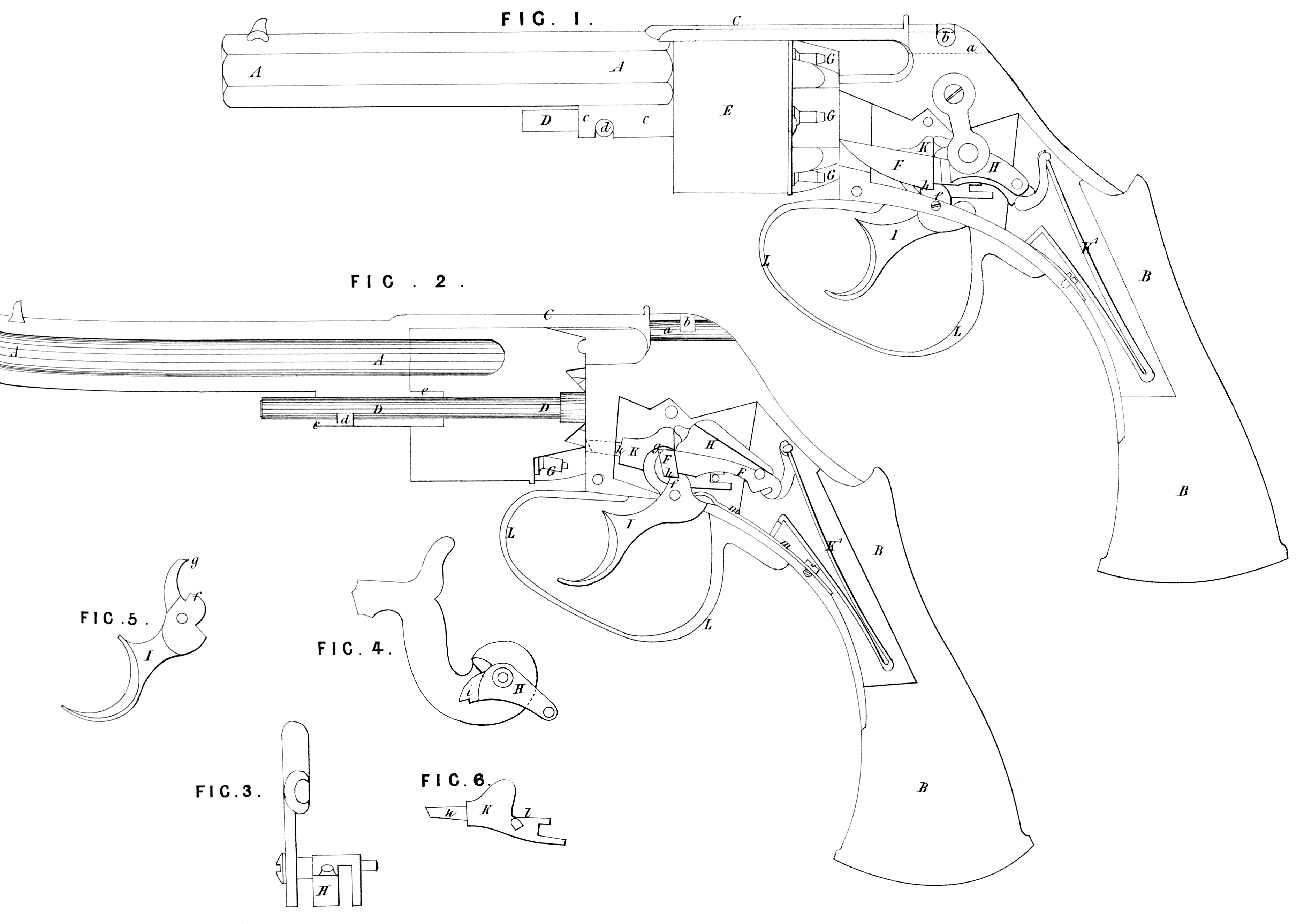
In all revolving fire-arms where the breech revolves it is the practice to cause the revolution by pulling the trigger, and the pull necessary has been so strong as to jolt the fire- arm, and cause unsteadiness of aim. To obviate this I make the tumbler in the lock with a notch or “bent,” and in the lifter which fits into a ratchet on the back of the breech I make another notch or “ bent,” and I form the inner end of the trigger with two projections or noses. By these means very little power ill be required to cause the barrels to revolve, and no unsteadiness of aim need result. Another advantage is also gained by this arrangement, as the barrels are caused to revolve by pulling up the cock. In order to prevent the breech from “sticking” after several shots have been fired I place a tube on the under part of the barrel which fits into the centre of the breech, and round which it revolves. Figure 1, of the Drawings hereunto annexed represents a side view of a pistol thus constructed, with the stock in section, and the lock plate removed in order better to shew the different parts; Figure 2, is a longitudinal section of the same; and Figures 3, 4, 5, 6, detached views of the improved portions of the lock. A, A, is the barrel, which is secured to the stock B, by means of the top strap C, which has a circular projection or pin a, formed in a piece with it, and is passed in a corresponding circular hole drilled through the back end of the lock being prevented from withdrawal when in its place by a catch b, which is hinged to the lock, and brought down into a recess cut in the centre portion of the pin a. c, c, is a tube upon the under side of the barrel, which is passed over the end of the spindle D, and prevented also from coming off by another catch d, hinged to the tube c, and fitting into a notch in the spindle D. E, is the revolving breech, of the ordinary construction for revolving fire-arms, free to revolve round the spindle D, when acted upon by the point of the lifter F, which takes into the teeth of a circular rack upon the back end of the breech. The end of the tube c, is prolonged, and fits into a socket e, in the breech, whereby the flash and products arising from the discharge are prevented from corroding or collecting upon the spindle, which might otherwise cause the breech to stick, and thus interfere with its revolution. G, G, are the nipples. H, is the tumbler, separately represented in Figures 3, and 4, upon the axis of which the cock or hammer is secured. I, is the trigger, the inner end of which is formed with two noses or projections f, and g, the former f, fitting into the notch or bent h, in the back end of the lifter F, while the latter g, takes into the notch or “bent” i, in the end of the tumbler when the pistol is on full cock; but this action of the projection g, only takes place when the pistol is cocked by drawing up the hammer, in which position the lock is retained until the trigger is pulled. K, is a sliding piece or cylinder stop, which has formed upon its front end a projecting pin k, passed through a hole in the back end of the lock which is used as a stop to prevent the breech from revolving too far; the chambers in the breech are thus made successively to coincide with the bore of the barrel. This piece is caused to slide by means of the “ bent ” part of the tumbler coming in contact with the stop I, when cocking the pistol either by means of the trigger or by lifting the hammer, whereby the projecting pin k, is caused to protrude beyond the face of the “ back end ” of the lock. The protruding portion of the pin is drawn back to admit of the revolution of the breech by the projection g, of the trigger coming against the stop l, when the trigger is released from the finger and brought back to its proper position by the action of the spring m. Figure 6, represents a detached view of this sliding piece. K^1, is the main spring, and L, the trigger guard.
And having now described the nature of my said Invention, and in what manner the same is to be performed, I declare that I claim the forming the triggers of revolving fire-arms with two projections or noses, which act upon notches or “bents” in the tumbler, and the lifter in the manner and for the purpose herein-before described. I also claim the placing a tube upon the under side of the barrel, which is prolonged, and fits into a socket in the breech for the purpose of preventing the breech from sticking, all as herein-before described, and represented in the Drawings hereunto annexed.
In witness whereof, I, the said Henry Needham, have hereunto set my hand and seal, this Twentieth day of March, One thousand eight hundred and fifty-four.
HENRY NEEDHAM. (L.S.)