Germany 74966
PATENTSCHRIFT
— Nº 74966 —
KLASSE 72: Schusswaffen und Geschosse.
CARL von PECKER in WIEN.
Mehrläufige mit Revolvertrommel versehene Feuerwaffe.
Patentirt im Deutschen Reiche vom 23. Juli 1893 ab.
Vorliegende Erfindung betrifft eine Einrichtung an-Handfeuerwaffen,, insbesondere an Revolvern, welche es ermöglicht, zwei Schüsse gleichzeitig (sechs Doppelschüsse) oder nur einen Schufs (zwölf Schüsse hinter einander) abzufeuern.
In der beiliegenden Zeichnung ist:
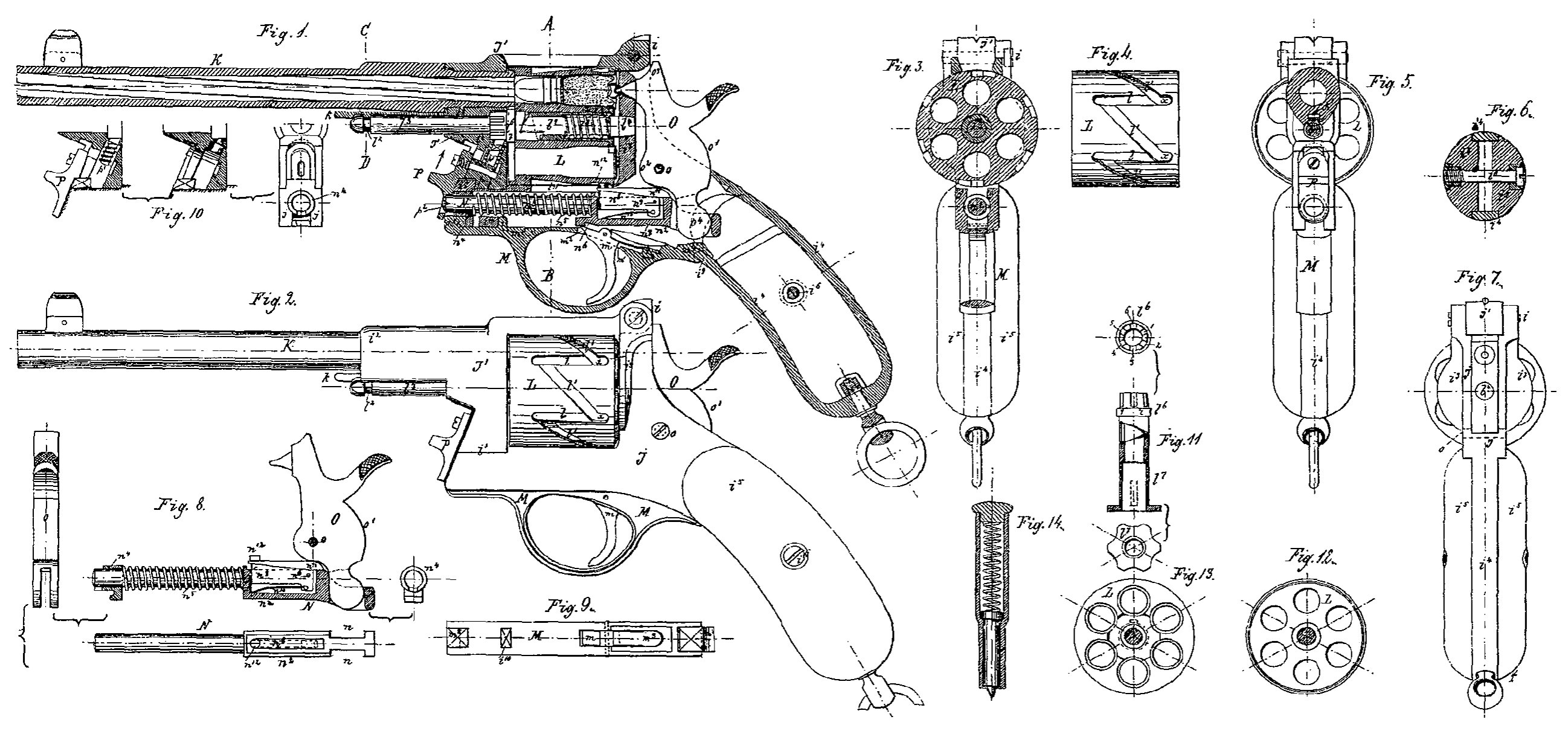
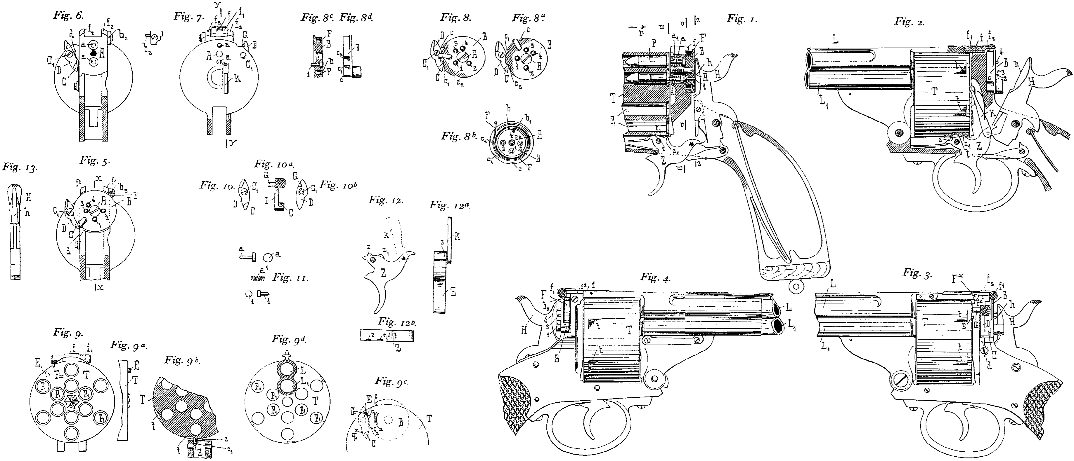
Fig. 1 ein Längenschnitt durch einen mit den diesbezüglichen Neuerungen versehenen Revolver nach der Linie x-x in Fig. 5)
Fig. 2 ein Längenschnitt nach y-y in Fig. 7
Fig. 3 eine linksseitige Aufsenansicht des in Fig. 1 dargestellten Revolvers,
Fig. 4 eine rechtsseitige Aufsenansicht desselben,
Fig. 5 ein Querschnitt nach z-z in Fig. 1,
Fig. 6 ein Querschnitt nach o-o in Fig, 1 bei weggenommener Schlagstiftscheibe,
Fig. 7 ein Querschnitt nach w-w in Fig. 1, vom Pfeil p aus gesehen,
Fig. 8 bis 8d zeigen die Schlagstiftscheibe in ihren verschiedenen Stellungen, sowie eine Innenansicht und einen Querschnitt derselben,
Fig. 9 bis gd stellen die Patronentrommel dar,
Fig. 10 bis 10b zeigen die Sperrvorrichtung für die Schlagstiftscheibe in Vorder-, Seiten-und Rückansicht,
Fig. 11 zeigt die einzelnen Schlag-und Zündstifte in Seiten-und Vorderansicht,
Fig. 12 bis 12b stellen das Revolverzüngel in Vorder-und Seitenansicht, sowie im Grund-s1ls dar, während
Fig. 13 eine Vorderansicht des Hammers ist.
B ist eine um die Achse bezw. Schraube A drehbare Schlagstiftscheibe, welche eine Ringnuth D, Fig. 8b und 8c, zur Aufnahme der Feder F besitzt. Diese Feder F ist einerseits bei b¹ in der Schlagstiftscheibe B befestigt, während das andere freie Ende an einem am Revolvergestell festen Stift b² hängt.
Die Schlagstiftscheibe nimmt aufserdem noch vier Schlagstifte 1, 2, 3, 4 auf, welche durch die mit Federn a¹ montirten Zündstifte a in Fühlung stehen und nach rückwärts geprefst werden.
Die Schlagstifte 1, 2, 3, 4 übertragen den Schlag des Hammers 7, welcher mit der Rachen Hammerbahn h auf sie einwirkt, mittelst der Zündstifte a auf die Zündpillen der Patronen P, Fig. 1, und kehren nach dem Rückgang des Hammers in seine Ruhelage (Fig. 3 und 4) durch die Einwirkung der Federn a¹ bezw. Zündstife a wieder in die Anfangsstellung zurück.
Die gegenseitige Anordnung der Zünd-und Schlagstifte ist nun derart getrofien, dafs die im Revolvergestell befindlichen zwei Zündstifte a a sich senkrecht diametral gegenüber befinden (Fig. 6 und 7), während die im gleichen Lagekreis angeordneten vier Schlagstifte 1, 2, 3, 4 der Schlagstiftscheibe B derart zu einander stehen, dafs 1, 2, 3 je um 1/4, Kreisbogen und 4 um 1/8; Kreisbogen zu 3 versetzt erscheint. Diese Anordnung ermöglicht es, durch Drehen der Scheibe B entweder den Schlagstift 1 mit dem unteren Zündstift a allein in Fühlung zu bringen (Fig. 5 und 1), ferner den Schlagstift 4 mit dem oberen Zündstifi a allein in Verbindung zu setzen (Fig. 8) oder die gegenüberstehenden Schlagstifte 2, 3 zu beiden Zündstiften aa zum Abfeuern von Doppelschüssen in übereinstimmende Lage zu bringen (Fig. 8a).
Um nun diese jeweilige Stellung der Schlagstifte bezw. der Schlagstiftscheibe festzulegen, besitzt letztere drei Zahnungen c c¹ c², in welche ein Zahn C eines um die Achse C¹ am Revolvergestell drehbaren Stellhebels D eingreift (Fig. 5 und 6).
Die Zahnungen c c¹ c² sind nun in der Scheibe B derart eingeschnitten, dafs ein Feststellen derselben in der jeweiligen, vorher besprochenen Lage (Fig. 5, 8 und 8a) möglich wird.
Der Eingriff des Daumens C in die Zahnung e der Scheibe B entspricht der Stellung in Fig. 5; es können also die sechs Schüsse des inneren Patronenkreises nach einander abgefeuert werden. Hierzu ist es vorher nothwendig, auch die Patronentrommel T nach dem Laden in ihre Normalstellung zu bringen, welche dadurch bedingt ist, dafs der Stift E (Brechsystem des Revolvers angenommen) an eine Feder Fˣ stöfst (Fig. 9).
Wird der Revolver wieder schufsfertig ge-macht, so schnappt das von der Feder f be-einflufste Griffstück f¹ hinter die Nasen f² f² des Revolvergestelles ein, wodurch aber auch die Nasenfeder Fˣ von der Gleitfläche fˣ emporgehoben wird, so dafs sie den Stift E ungehindert seine Kreisbahn vollführen läfst (Fig. 3). Sollen zwölf Schüsse hinter einander abgefeuert werden, so wird die Schlagstift-scheibe B in die in Fig. 8 gezeigte Lage ge-dreht; dadurch springt einestheils der Zahn C in die Zahnung e¹, anderentheils wird die Feder F in Spannung versetzt und sucht die Scheibe B in die Stellung Fig. 5 zurück-zudrehen, was aber durch den Zahn C ver-hindert wird. Durch die Stellung der Scheibe B tritt der Schlagstift 4 mit dem oberen Zünd-stift a in Fühlung und es werden nach ein-ander die sechs Patronen des äufseren Kreises abgeschossen. Ist die sechste äufserste Patrone abgefeuert, so hat die Trommel T, somit auch der Stift E einen vollen Kreis beschrieben. Wird jetzt die Trommel T in bekannter Weise durch die Schaltklinke k vom Züngel Z aus (Fig. 2) zum siebenten Schufs weiter geschaltet, so dreht sich auch der Stift E weiter, stöfst aber auf diesem Weg an einen an der rück-wärtigen Seite des Stellhebels D angebrachten Daumen G, Fig. 10a, 10b, 9 und 9e, dreht dadurch den Stellhebel D in der Pfeilrich-tung g nach aufsen (Fig. 9c), um den Weg frei zu bekommen. Durch diese Aufsen-drehung des Stellhebels D wird aber die Scheibe B frei, macht infolge der gespannten Feder F eine Linksdrehung, und zwar so lange, bis der Daumen C des Stellhebels D infolge der Federkraft d wieder in die Zah-nung c einspringt. Diese Bewegung des Stell-hebels D war bereits wieder möglich, da der Stift E schon seinen Weg während dieser Zeit über den Daumen G fortgesetzt hat.
Durch die Rückdrehung der Schlagstiftscheibe B in die Normallage (Fig. 5) durch die Feder F wurde aber auch der Schlagstift 4 aufser Verbindung mit dem oberen Zündstift a gebracht, dadurch aber der Schlagstift 1 mit dem unteren Zündstift a in Fühlung gesetzt, wodurch jetzt, wie schon beschrieben, die unteren sechs Patronen abgeschossen werden.
Man kann also, wie zu ersehen, zwölf Schüsse ohne jede Unterbrechung des Feuerns abgeben, da die Scheibe B von der Trommel T aus selbstthätig umgeschaltet wird, sobald die sechs äufseren Patronen abgeschossen sind und. die inneren Patronen in Kraft treten sollen. Um sechs Doppelschüsse abzugeben, wird die Scheibe in die in Fig. 8a gezeigte Lage gedreht, wodurch der Zahn C in die Kerbe c² springt und die Schlagstifte 2 und 3 mit beiden Zündstiften aa in gegenüberstehende Stellung gelangen; es können somit je eine innere und eine äufsere über einander liegende Patrone gleichzeitig abgefeuert werden. Sind die letzten zwei Patronen abgeschossen, so hebt der Stift E, wie früher beschrieben, den Zahn C aus der Kerbe c²; die durch die frühere Drehung gespannte Feder F dreht die Scheibe B in ihre Normalstellung (Fig. 5) zurück, wodurch wieder der Stift 1 vor den unteren Zündstift a zu stehen kommt.
Um in den Feuerpausen, sowie während des Feuerns ein Rückdrehen der Trommel T zu verhindern, besitzt das Züngel Z zwei Nasen z z¹, welche derart angeordnet sind, dafs die Nase z in die Ruhestellung des Revolvers bezw. nach Abfeuern des Schusses in die Ausnehmungen t der Trommel T tritt und eine Weiterdrehung derselben im Sinne des Uhrzeigers dadurch vermeidet (Fig. 1).
Im Moment, in dem der Schuis abgefeuert, also das Züngel Z zurückgedrückt wird (Fig. 2), tritt der Stift z¹ in die Kerbe t und hindert somit ebenfalls eine Weiterdrehung der Trommel T in der Richtung des Uhrzeigers.
Die Weiterschaltung der Trommel T zu einem neuen Schufs erfolgt in dem Zeitraum, in dem die Nasen z z¹ eine waagrechte Lage einnehmen, also das Züngel Z sich beim Zurückdrücken etwa in der Mittelstellung befindet, da bei dieser Stellung die Trommel T knapp über die beiden Nasen z z¹ hinweggehen kann.
Die bei diesem beschriebenen Revolver in Anwendung kommende Patronentrommel T besitzt, wie in Fig. 9, 9b und 9c gezeigt, zwölf in zwei concentrischen Kreisen in Gruppen zu je sechs angeordnete Laderäume P¹, denen zwei unter einander angebrachte Läufe L L¹ gegenüberstehen.
Patent-Ansprüche:
1. Eine Feuerwaffe, gekennzeichnet durch eine um eine Achse (A) drehbare Schlagstiftscheibe (B) mit vier Schlagstiften (1, 2, 3, 4) und einer Feder (F) in der Ringnuth (b), welche Scheibe mittelst der Zähne (c c¹ c³) und des Stellhebels (D) derart gestellt werden kann, dafs die im Revolvergestell gelagerten Zündstifte (a a) entweder einzeln oder gleichzeitig von den Stiften der Scheibe (B) getroffen werden.
2. Bei der unter 1. gekennzeichneten Feuerwaffe die Anbringung eines Stiftes (E) an der Trommel (T), welcher durch den Daumen (G) am Stellhebel (D) ein Ausheben seines Zahnes (C) aus den Kerben (c c²) und dadurch eine selbstthätige Umschaltung bezw. Rückdrehung der Schlagstiftscheibe (B) bedingt.
3. Bei der unter 1. gekennzeichneten Feuerwaffe die Anordnung einer mit zwei Reihen Kammern (P¹) versehenen Patronen-trommel (T), deren Normalstellung durch Anstofsen des Stiftes (E) an eine Nasenfeder (F) im Ladezustand erfolgt und deren Rückdrehung durch zwei am Abzug (Z) angebrachte Nasen (z z¹), welche abwechselnd in die Kerben (t) der Trommel (T) eintreten, gesichert wird.