US 183389
UNITED STATES PATENT OFFICE.
FRANK W. FREUND, OF CHEYENNE, WYOMING TERRITORY.
IMPROVEMENT IN REVOLVING FIRE-ARMS.
Specification forming part of Letters Patent No. 183,389, dated October 17, 1876, application filed September 27, 1785.

To all whom it may concern:

Be it known that, I, Frank W. Freund, of Cheyenne, in the county of Laramie and Territory of Wyoming, have invented certain new and useful improvements in Fire-Arms; and I do hereby declare that the following is a full, clear, and exact description thereof, reference being had to the accompanying drawings, making part of this specification, in which—

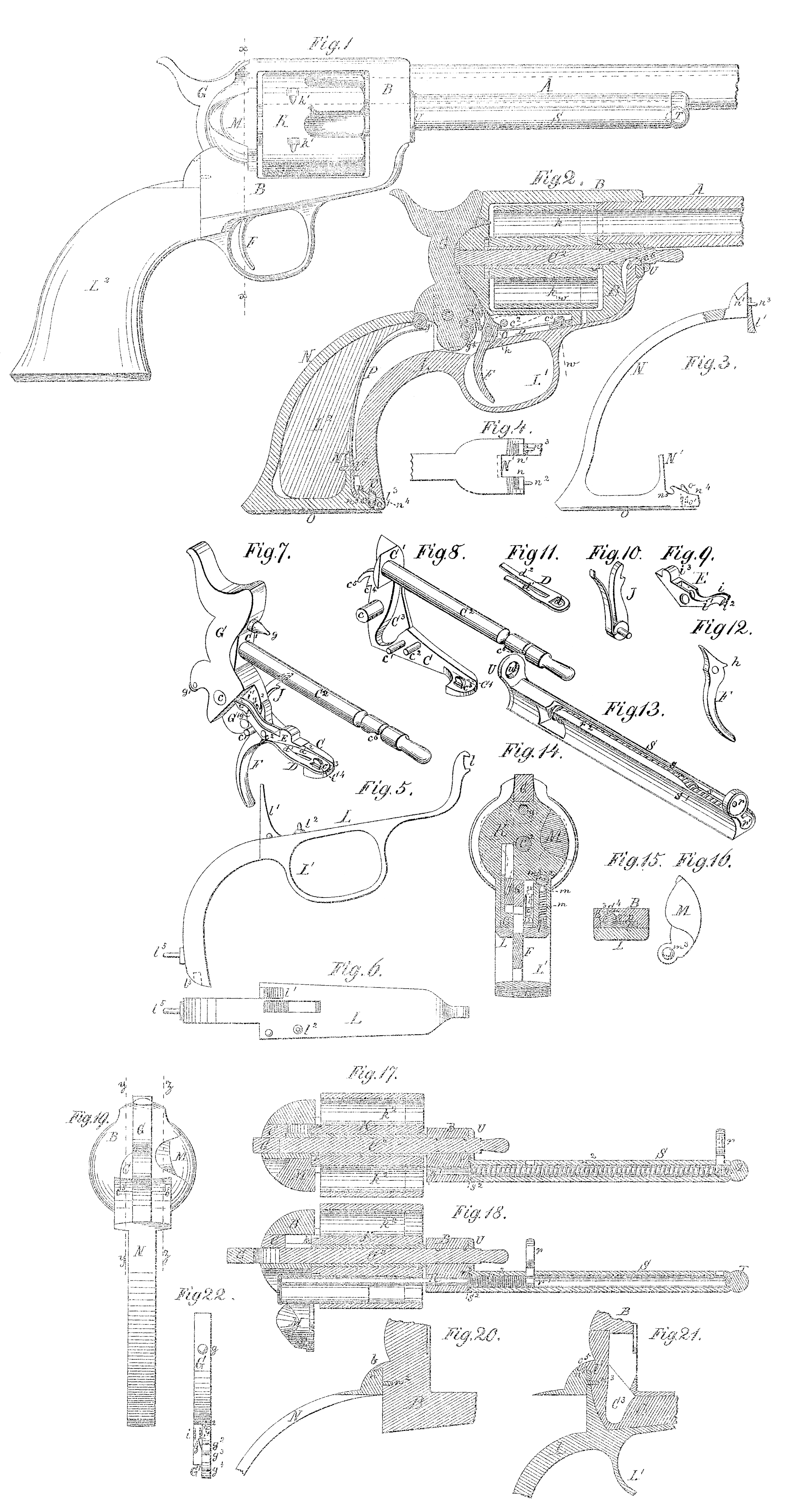
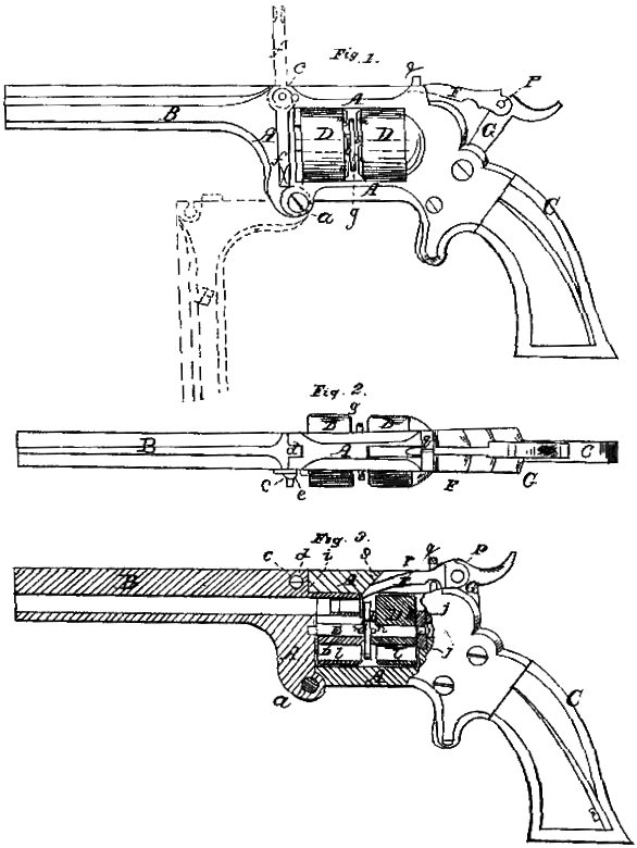
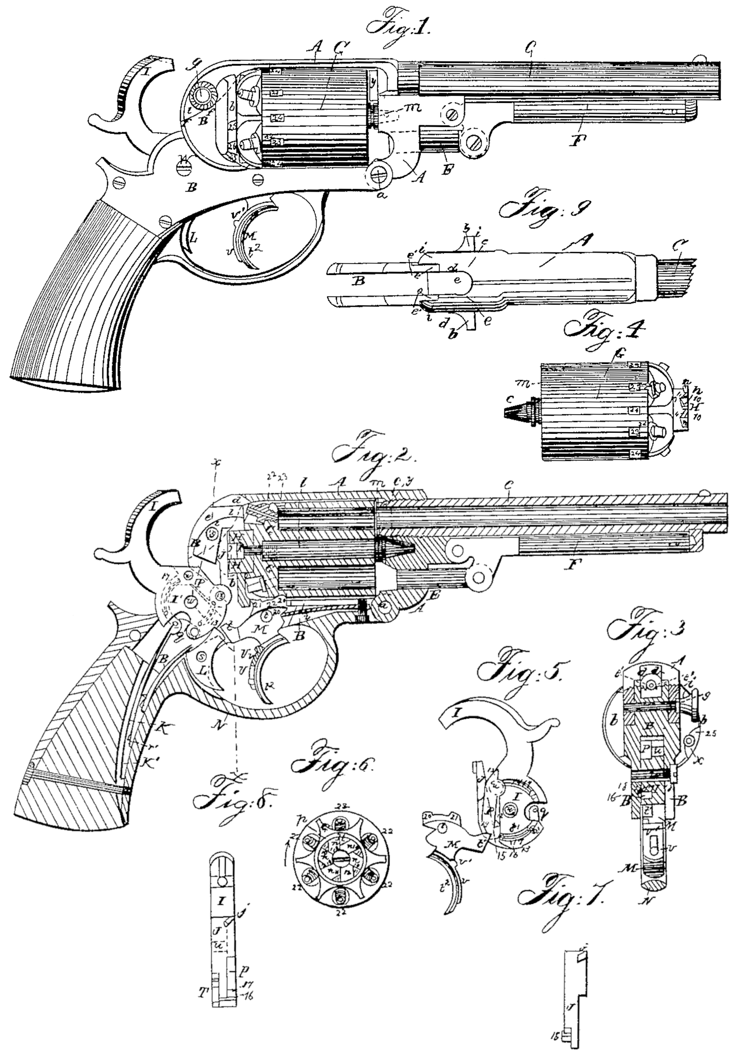
Figure 1 is a side elevation of a fire-arm or revolver with my invention applied to it. Fig. 2 is a vertical longitudinal central section of the same. Fig. 3 is a detailed view of the back or butt strap of the said fire-arm. Fig. 4 is a top view of the extreme upper end of the said strap. Fig. 5 is a side view of the guard-plate in detail. Fig. 6 is a top view of the guard-plate. Fig. 7 is a perspective view of the lock-plate and the parts supported thereby. Fig. 8 is a perspective view of the lock-plate and rod of the revolving chambered cylinder combined, in detail. Fig. 9 is a perspective view of the cylinder check or pawl. Fig. 10 is a perspective view of the spring pawl, whereby the said cylinder is propelled or revolved. Fig. 11 is a perspective view of the combined split check and trigger spring. Fig. 12 is a perspective view of the trigger. Fig. 13 is a perspective view of the cartridge-case extractor or expeller. Fig.14 is a vertical cross-section in the line x x of Fig. I looking toward the muzzle. Fig. 15 is a sectional view of the locking device of the front part of the lock-plate in the line w w of Fig. 2. Fig. 16 is a full view of the breech-gate leading to the chambers of the revolving cylinder. Fig. i7 is a central horizontal section through the cartridge-case expeller and the revolving cylinder, in a position for either loading the arm or expelling the empty cartridge-case. Fig. 18 is the same section as Fig. 17, showing the operation of expelling the cartridge-case. Fig. 29 is a back view of the revolving fire-arm. Fig. 20 is a detail section of the same in the line y y of Fig. 19. Fig.2i is a detailed section of the fire-arm in the line z z of Fig. 39; and Fig. 22 is a detailed view of the hammer and cylinder check.

The nature of my invention consists in the construction, combination, and arrangement of parts, hereafter described and specifically claimed, whereby a fire-arm is produced in which the movable parts are provided with the bearings of the lock mechanism, and wherein the said movable parts are so interlocked with each other and with the cylinder-frame that they may be taken apart in succession, either singly or in groups, or both by detaching the parts which form the last connection in putting the fire-art together.

The object of my invention is to enable the operator to take the fire-arm to pieces, at to put it together by hand without the avid of instruments. Another object of my invention is to avoid weakening the cylinder-frame by drilling holes into it for the reception of pins and screws. A still further object of my invention is to five the fire-arm a neat appearance by means of smooth and will-polished surfaces, and by avoiding unsightly appearances of the same by dispensing with the use of exposed pins or screws in uniting the parts together.

In the drawings, A represents the barrel of a gun or pistol which is fastened to a cylinder-frame, B, which in the main is of ordinary construction. The lock mechanism of the said fire-arm is attached to a lock-plate, C, which is provided with bearings c for the hammer c^1 for the trigger, and c^2 for the cylinder-check, and which is also, by means of lap, C^1, connected with the cylinder-rod C^2. The form part of the said lock-plate is provided with an eccentric or a cam-button, c^3, by means of which the combined trigger and check spring D is fastened thereto.

The spring d, as seen in Fig. 11, has an opening, d, of the same shape as the button c^3, but arranged in a different position, so that it may be passed over the said button with the spring D held a right angles with the lock-plate, and by turning the said spring into the right position it becomes fastened on the neck of said button. The button c^3 is provided with an inclined surface, C^4, which forms, with the corresponding surface, B^3, in the cylinder-frame, a dovetail connection, the purpose of which is to prevent downward movement of the lock-plate. The spring D has has two branches, d^1 d^2, the former for operating the cylinder-check E, and the latter for operating the trigger F. The upper part of the lock-plate C is provided at the back with a step, c^4 and a downwardly-bent lip, c^5, the use of which will be hereafter fully described. The cylinder-rod C^2 is near its forward end provided with an inner step, c^6, the purpose of which will be hereafter explained. Upon the bearing c the hammer G is fitted, which is provided with a firing-pin, g, a friction-roller, g^1, for the mainspring, and a first, second, and third rest, g^2 g^3 g^4, respectively. Upon the bearing c^1 tie trigger F is fitted, and by means of the lip h operated by the spring-arm d^2. Upon the bearing c^2 the cylinder-check E is fitted, the back part of which is vertically divided into two thin elastic arms, i i^1, one of which, i^1, bears on the reduced lower part G^1 of the hammer G. The said reduced part G^1 is provided with a lifting-ratchet step, g^5, by means of which the arm i^1 is lifted, when the hammer is cocked. When the hammer descends the ratchet g^5 slides past the rounded upper corner i^2 of the arm i^1, and, pushing the arm out of the ay, resumes its normal position below the said arm. The lower part of the hammer G is also provided with a spring-pawl, J of ordinary construction, which is operated in a depression, C^3, in the locking-plate, and revolves the cylinder K by means of a ratchet-head, k, constructed as unusual in that class of fire-arms. The chambered cylinder K is provided with a notch, k^1, near each chamber k^2, into which the head i^3 of the spring-cheek E fits, and thereby holds the cylinder in position during the firing of the arm. The lock-plate C is so inserted into the lower part of the cylinder-frame that its lower side is flush with said part. A guard-strap, K, is fitted on the lower side of the cylinder-frame and fastened to the front part of it by beans of a hook, l, which enters the metal of said frame in such manner as to abut against the step c^5 of the cylinder-rod C^2, thereby preventing it from moving longitudinally. The guard-strap L is provided with a projection, l^1, which, in its normal position, is behind the lock-plate Cm and fits into the step c^4. A teat-pin, l^2, on the upper surface of the guard-strap L is provided with a projection, l^1, which in its normal position, is behind the lock-plate C, and fits into the spec c^4. A teat-pin, l^2, on the upper surface of the guard-strap, serves as a stead-pin by entering the metal of the cylinder-frame. Above the pin l^2 a hole is drilled into the cylinder-frame, and into it a spiral spring, m, with a piston, m^1, attached to it, is inserted, which bears on the corner m^2, formed by two flat surfaces on the corner m^2, formed by two flat surfaces on the pivot, m^3, of the breech-gate M, and thereby keeps the said breech-gate either opened or closed, as shown in Fig. 14. Below, and on the guard-strap, the trigger-guard L^1 is formed. The rear end of the guard-strap is inserted into the wooden or ivory handle L^2, and ends at the lower forward corner of the same, where it is provided with a slope, l^3, a vertical socket, l^4, and a horizontal pin, l^5. A back-strap, N, is inserted into the back and bottom of the handle L^2, and is interlocked with the cylinder-frame by means of a lip, b, at the rear upper corner of the cylinder-frame B, and a notch, n, at the forward end of the said back-strap. Another notch, n^1, opposite the notch n, interlocks with the lip c^5 on the lock-plate C. Below the said notches, which are separated by a vertical slot N^1, for the reception of the hammer G, the back-strap N is provided with two horizontal steady-pins, n^2 n^3. The pin n^2 enters the back of the breech of the cylinder-frame B, as seen in Fig. 20, and the pin n^3 passes through the projection l^1 of the guard-strap L into the lock-plate C, as seen in Fig. 21.

The lower part of the back-strap N is provided with a spring, O, and a pin, o, which latter passes through the metal of the back-strap and into the socket l^4 of the guard-strap. The pin o is near the spring O reduced in thickness, as at o^1, and the hole in guard-strap in which it operates is made accordingly, as shown in Fig. 2. so that the said pin cannot be entirely pulled out of the back-strap. The lower forward end of the back-strap is provided with a slope, n’, which matches the slope l^3 of the guard-strap. An upright lug, N^1, on the back-strap is entered by the pin l^5, and prevents separation of the straps L and N in a vertical direction; and it also serves, in connection with the pin l^5 and a notch, n^5, at its foot, as means for fastening the mainspring P, which is thereby clamped between the strap L and the lug N’, and also prevented from slipping vertically. The spring P is provided with a hook, p, which fits into the notch n^5. The expeller of the cartridge-cases consists of a rod, R, with a thumb-plate, r, and a, head, r^1, loosely fitted into a case, S, and provided with a spiral spring, r^2. The case S is open at both ends, and is provided with a slot, s, in which the neck of the thumb-plate r moves, and the said slot may extend from end to end of the case, or may be stopped hear one of the said ends, so that the rod R may be removed with its thumb-plate r from the open end. The front end of the case S fits upon a projection, t, on a lug, T, upon the barrel A of the fire-arm, and the back end of the said case as a flange, U, with a hole, u, through which the cylinder-rod C^2 passes, while the flange itself fits on the front end of the cylinder-frame B, and by this means is prevented from longitudinal movement. I prefer to provide the case S with a curved basis, s^1, which fits upon the barrel A, whereby the said case is prevented from turning. The rear end r^3 of the spring r is enlarged in diameter, and the rear end of the case S is provided with a countersunk enlargement, s^2, for its reception, so that, the spring r^2º bears upon the front face of the cylinder-frame and upon the rear shoulder of the head r^1 of the rod R. The rear end of the case S may be closed around the rod R, and thus provide a bearing for the rear end of the spring r^2. The rod R is as long as the case S, and does not enter the cylinder-frame in its normal position, so as to hinder the separation of the case from its fastenings. The rod R, when operated, is guided through a hole b’, in the cylinder-frame.

Operation: The loading and firing of the described fire-arm are effected in the same manner as that of any ordinary fire-arm of the same class, and therefore need no description. The separation of the lower parts of the said fire-arm begins as the lower forward end of the handle. The spring O is at its forward end bent down until the pin o has left the socket l^4, whereupon the lower end of the back-strap N is swung back and off from the pin l^5, the pins n^3 n^3 leave their sockets in the cylinder-frame B, and the lock-plate C and the upper end of the back-strap are removed downward from the locking-lips band c^5. Thus the back-strap N, the handle L^2, and the mainspring P become detached from the arm. The mainspring P is now swung out of its lower notch n^5, and the handle L^2 removed from the back-strap b swinging its upper end down and then pulling it off sidewise, The guard-strap L is now swung forward after the hammer G has been raised into the second rest, and the trigger thereby moved forward to permit the guard-strap to pass over it, for the purpose of being unhooked at its front end l. The hammer remaining at half-cock, the cylinder-rod C^2 is pushed out of its bearing, whereby the lock-plate, with the lock mechanism, is removed from the cylinder-frame. By having the hammer half-cocked, the cylinder-check E is so much lowered as to slide over the cylinder and permit the withdrawing of the lock-plate. The cylinder-check E is now removed from its bearing c^2, the trigger F is then removed form its bearing c^1, the spring D is turned at a right angle to the lock-plate and passes over the button c^3, the hammer G is then removed from its bearing c, and spring-pawl J separated from it. The case S is swung from the cylinder-frame and removed from the barrel A, the rod R is removed by sliding it out in a forward direction, and the spring r^2 is removed from the rear.

The described operation is reversed when the fire-arm is to be again put together. The principal movable parts of the lock mechanism shown are similar to those used in Colt’s revolvers, and I have simply made use of them for the purpose of illustrating my invention, and of showing the improved mode of fastening them without the use of removable screws and pins. It is easily seen that my improved system of fastening and interlocking the described parts can be adapted to all kinds of fire-arms with a very slight and unimportant alteration of the shape, whereby these parts are made to conform to the shape or outlines of such fire-arms. For instance, the stock of a revolver, gun, or carbine would require a longer back-strap and a straighter guard-strap without necessitating a change in the construction of the described final interlocking device.

There are many modifications of the means whereby the parts described may be fastened and interlocked without departing from the principle of my invention, and I therefor do not confine my claims to the precise construction of the said parts.

The advantages of the described invention are, a strong compact fire-arm of elegant appearance, which is not disfigured by screw or pin heads or ends, and which can be taken apart very rapidly by hand; and consists of less parts than any similar fire-arm in which the parts are secured by screws and pins, and of which no part can be lost by accident, as is so often the case with screws and pins in ordinary fire-arms.

Having described my invention, what I claim as new, and desire to secure by Letters Patten, is—

1. A continuous connection of parts in pistols extending throughout the arm, finally locked by a single device substantially as described, whereby all the parts are secured in their positions, and by the unlocking of the said locking device all the pieces become detachable successively or in groups, substantially as set forth.

2. A locking device, substantially as described, for a revolving fire-arm, by the unlocking of which all the parts previously connected may be disconnected, substantially as set forth.

3. In a revolver, a removable or detachable lock-plate carrying the lock mechanism and the revolving mechanism, substantially as described.

4. The lock-plate C and the cylinder-rod C^2, united together and supporting one another; substantially as set forth.

5. A detachable lock-plate adapted to be inserted into its seat in the breech-frame, and to be held therein by the removable parts contiguous to it, substantially as described.

6. The back-strap N, having its upper end fastened to the cylinder-frame B, the lock-plate Cm and the guard-strap L, having its lower end interlocked with the lower end of the back-strap B, substantially as described.

7. The combination of the lock-plate C, carrying the cylinder-rod C^2, the latter having a notch, c^6, and the guard-strap L, having a hook, l, and a projection, l^1, substantially as described.

8. The final locking device, consisting of the spring Om provided with the pin o attached to the back-strap, and the guard-strap L provided with the socket l^4, substantially as set forth.

9. The combination of the back-strap N, having lug N^1, the guard-strap L, having the pin l^5, and a latch-fastening, substantially as described.

10. The combination of the back-strap N, having the lug N^1, and the notch n^5, with the pin l^5 of guard-strap L, and the spring P, substantially as set forth.

11. The combination of the cylinder-rod C^2 and the extractor0case S, having a flange, U, substantially as set forth.

12. The combination of the barrel A, provided with a lug, T, having a projection, t, and the extractor-case S, for holding said case in position, substantially as set forth.

13. The extractor or ejector case S, provided with an enlargement, r^3, at the rear end of its bore, as and for the purpose described.

14. The means herein described for securing the spring D to the lock-plate C, consisting of the button c^3, so shaped that when the corresponding shape opening in the spring is placed over it, and a partial turn given to said spring, the latter will be fastened in place as set forth and described.

15. The combination of the main spring P, having a hook, p, and the back-strap N, having a notch, n^5, substantially as set forth.

16. The combination of the guard-strap L, the teat-pin l^2, the cylinder-frame B, the spring m, and the piston m^1, substantially as set forth.

17. The combination of the frame B and the guard-strap L, having the hook l, and a fastening device on the rear stock, whereby the two parts are connected together so as to be separated by a downward-swinging movement of the guard-strap, substantially as described.

18. The combination of the cylinder-frame B, the guard-strap L, having the hook l, and the cylinder-rod C^2, having he notch c^6, substantially as set forth.

19. The combination of the lock-plate C, having a button with an inclined surface, C^4, and the cylinder-frame B, having an inclined surface, B^3, substantially as set forth.

20. The combination of the guard-strap L, provided with the lug l^1, the lock-plate C, and the back-strap B, with the pin n^3, substantially as set forth.

Witness my hand in the mater of my application for a patent for an improved breech-loading revolver, this 11th day of July, 1876.

FRANK W. FREUND.

Witnesses:
J. W. Bruner,
J. R. Whitehead

Canada 44648
TO ALL WHOM IT MAY CONCERN:

Be it know that I, Peter Henry Finnegan, of the City of Chicago, in the State of Illinois, United States of America, Manufacturer, have invented certain new and useful improvements in Revolvers, and I do hereby declare that the following is a full clear and exact description of the same.

This invention relates to Fire-Arms, the object being to provide an improved construction of that class thereof herein shown and described.

In the drawing forming part of this specification, Figure 1 is a side elevation, with cover removed, the case being shown partly in section, and the cylinder partly broken away.
Figure 2 is a section on line 2-2, Figure 1.
Figure 3 is a perspective view of the under side of the cover.
Figure 4 is a sectional perspective view of the case.
Figure 5 is a perspective view of a part of the trigger.
Figures 6 and 7 are plan views of opposite side of the cylinder.
Figure 8 is an edge view of the cylinder.
Figure 9 is a section on line 9-9, Figure 8.
Figure 10 is a similar view to Figure 1, but illustrating the positions of the parts of the weapon when the hammer is at full cock.

The improvements in said revolver construction, hereinbelow described, relate to safety devices for preventing the arm from being fired inadvertently:
To an improved manner of constructing the case, the barrel, and the breech-block, whereby increased strength and durability are secured, and the cost of construction is reduced, wand whereby the grip of the arm is improved:
To an improved construction of the devices for locking the cover to the case which constrains the cylinder and other parts, – and to means connected with the arm, for ejecting shells from the cylinder.

In the drawings, A is the case containing certain operative parts of the arm, as below set forth: N is barrel, and D is the hollow, cylindrically formed breech-block on which the cylinder of the arm rotates. Said case, barrel, and breech-block, are integrally made from steel, iron or other suitable metal.

Said case has heretofore been made separate from the barrel, B, the latter being screwed into the border of the case. Also, the breech-block, D, has heretofore been made separate form the case and united to the latter by screws, passing through one side of the case into one end of the block. But by changing the block, by forming the longitudinal slot, 3, in it so that the nose, x, of the hammer, 4, can be introduced through the side of said block, to the working position shown in Figure 1l the breech-block is made of one piece with the case, A, there by effecting a considerable savings in construction. Likewise by making the case and barrel of one piece, the weakness of a joint between said two pieces does not exist, the manipulation of, and work upon, two pieces is avoided and the work in finishing the same is rendered more economical.
The said case has on its border two inwardly overhanging lips of flanges, 5, 5, which, with two flange sections, 6,6 on the border of the cover, J, serve to secure said cover onto the case.

To facilitate the quick removal of said cover from the case, the cover is provided with a cam-shaped formation, 7, at the end of one of said flanges, 6. When said cover is to pe placed on the case, the two flanges,6, on the cover, are first brought between the flanges, 5, of the case. The cover is then turned, (bearing on the edge of the case) and the flanges, 6, run under the flanges, 5, thus locking the cover on.
On turning the cover backward to unlock it, said cam, 7, strikes the end of one of said flanges, 5, and one edge of the cover is thereby lifted from the case and can be grasped be the fingers to lift it off. The thick end of said cam, 7, runs against one end of one of the flanges 5, on the cover and prevent the cover from being turned too far when locking it on.
The cover, J, has two springs, g,g, on its inner side which bear frictionally against one side of the cylinder, h, when the cover is on the case, and prevent any by-throw of the cylinder and assist in holding it closely on the breech-block, D.

The case, A, has two finger-rests, 10, 12, on its border, one behind the other, in the forward one, 12, of which preferably, is hung a safety latch, 13, one end thereof extending sufficiently through a slot, o (see Figure 4) in the side of the case to engage with the side of any one recesses, n, in the periphery of the cylinder, h. Said latch is held normally in the position shown in Figure 1, by a suitable spring, o, placed under the outer end thereof: that is to say, in engagement with the cylinder, so that the arm can not be discharged inadvertently. The outer end of said latch, 13, lies in convenient position to be pressed upon the finger before firing to disengage the cylinder and permit it to rotate to bring a cartridge opposite the barrel when the trigger is pressed.
The finger rest, 10, serves as a rest for the latch finger when holding the arm, but not in a position to fire it.

The fire-arm, constructed as herein shown, has a cylinder, h, of disk form with cartridge chambers, 14, extending radially form its axis, in which the cartridge shells are left after firing.
To provide convenient means attached to the fire-arm for ejecting said shells from the cylinder, an ejector, 15, is pivoted by one end of the edge of the trigger, 16, and remains normally shut, as shown in Figure 1, but when used as an ejector, (the cylinder being taken out of the pistol-case) it is swung outwardly, as show in Figure 5, at right angles to the side of the trigger so that its free extremity may enter the chambers of the cylinder and eject the shell therefrom when the cylinder is forced against it.

The trigger, 16, is hinged by one end to the border of the case, A, and has a pawl, 17, attached by one end thereto and its opposite and extends though the border of the case under the cylinder, h, and engages with any one of the recesses, 18, (see Figure 7) in the under side of the cylinder and intermittently rotates the cylinder when the trigger, 16, is successively pressed upon. A sping, 19, retracts the trigger. The said trigger has an arm, 20, pivotally connected thereto near its hinged and which also enters the case, A, and engages with the notched side of the hammer to wing that back for a blow against the cartridge while the cylinder is turning to bring one opposite the barrel, 8.
A spring, 22, holds the end of arm, 20, yieldingly against the edge of the hammer.
A main-spring, 21, is secured to the bottom of the case, and has its free end engaging with a notch in the hammer.

It will be seen, from the foregoing description, that when the arm is properly held for firing, on finger presses the cuter end of the latch, 13, and the trigger is then pressed forward, turning the cylinder on the breech-piece, D, and operation the hammer, as described. The cover, J, is taken off to remove the cylinder and reload it, and upon replacing the cylinder the cover is locked on as described. A suitable perforation through the side of the breech-block permits the firing pin of the hammer to extend therethrough and strike the cartridge primer.

What I claim as my invention, and desire to secure by patent, is:—

1. In a revolving fire-arm of the class described, a cylindrical case, a cartridge-cylinder having an intermittent rotary movement in said case and having recesses in its periphery, combined with a safety-latch pivotally hung on the border of said case, one end of which passes through said border, a spring under one end of said latch operating to restrain the opposite end thereof normally in engagement with any of the said recesses, substantially as set forth.

2. In a revolving fire-arm of the class described, the cylinder-case having the integrally formed tubular breech-block centrally located therein, said block having a slot through its side extending from its extremity to its base whereby the nose of the hammer may be passes therein through, substantially as set forth.

3. The case, A, having the finger rests, 10, 12, on its border, one behind the other, combined with a safety-latch pivotally hung on the border of said case, and having one end opposite the forward side of said projection 12, and its opposite end extending through said border in proximity to the periphery of the cylinder, h, said rear rest, 10, serving as an abutment to the finger for carrying the arm, thereby leaving the outer end of said latch free, combined and operating substantially as set forth.

4. In a revolving fire-arm, of the class described, means for locking and removing the cover of the cylinder-case, consisting of sections of inwardly extending flange 5.5, on the border of said case, at the end of one of which flanges is a stop to a rest the circular movement of the case-cover, combined with a a cover having sections of flanges thereon to engage under those of said case, one of said cover-flanges having a cam, 7, at one end to engage with the one end of one of said case-flanges, thereby causing the cover to be lifted from the case when turned in one direction, substantially as set forth.

Peter Henry Finnegan

Springfield, Mass.
7th July, 1893.

Signed in the presence of,
Wm. S. Bellmof
Henry A Chapman

US 115258
UNITED STATES PATENT OFFICE.
ELI WHITNEY, OF NEW HAVEN, CONNECTICUT.
IMPROVEMENT IN REVOLVING FIRE-ARMS.
Specification forming part of Letters Patent No. 15,258, dated May 23, 1871.

To all whom it may concern:

Be it known that I, Eli Whitney, of New Haven, in the county of New Haven, and State of Connecticut, have invented a new Improvement in Revolving Fire-Arms; and I do hereby declare the following, when taken in connection with the accompanying drawings and the letters of reference marked thereon, to be a full, clear, and exact description of the same, and which said drawings constitute part of this specification, and represent, in—

Figure 1, a side view of the frame and spindle, the spindle in place as when securing the cylinder; Fig. 2, the same with the spindle withdrawn, as for the removal of the cylinder; Figs. 3 and 4 vertical sections on line x x.

This invention relates to an improvement in revolving fire-arms, the object being a convenient device for removing the cylinder; and it consists in combining with the spindle, which forms the bearing on which the cylinder revolves, a vertical latch, arranged in the frame, which will fall into a notch in the spindle when in its home position, and also into a similar notch when the spindle is withdrawn. sufficiently to permit the removal of the cylinder, thus preventing the entire removal of the spindle and avoiding the liability to lose the said spindle.

A is the frame, of common construction; B, the spindle or bearing, which passes centrally through the cylinder and forms the axis upon which the cylinder turns. It rests in a bearing, t, in the frame, with an end, D, projecting from the frame, which, under certain circumstances, may be used to force the exploded shells or cartridges from the chambers.

In the forward part of the frame I arrange a vertical slide, a, (see Fig. 3,) which extends down to the under side of the frame and is formed into or fixed in a head, d. A pin, f, or similar device, is inserted in the frame, passing through a slot in the said slide to prevent its removal entirely from the frame, and a suitable spring, n, is arranged to force the slide down ward, as in Fig. 3. The said slide is arranged in such relative position to the seat for the spindle B as to enter upon one side of the said seat, and the said slide is at one point, m, grooved, so that when the slide is pressed upward the said groove will conform to that portion of the seat for the spindle through which it passes, as seen in Fig. 4, but when down, as in Fig. 3, that portion of the seat is filled by the said slide.

On the spindle, at a point, i, (see Fig. 2,) a notch is formed in the spindle, this point being in such relative position that when the spindle is fully inserted, as in Fig. 1, the slide a will rest in the said notch. Near the end of the spindle a similar notch, s, is formed, which is in such position that when the spindle is withdrawn, as in Fig. 2, the slide a will rest in the said notch s.

The operation is as follows: Supposing the spindle to be in the position seen in Fig. 1, the slide will be in the position seen in Fig. 3. Holding the spindle in that position, press upon the head D to force the slide into the frame, as in Fig. 4, which brings the notch m into line with the seat of the spindle. Then the spindle may be withdrawn until the notch S comes in line with the slide. Then the slide will fall into the said notch s and prevent its further removal, unless it be desirable to entirely remove the spindle, which may be done by pressing the slide inward, as before. To return the spindle, press the slide in, as before, return the spindle, and when in place the slide will fall into the notch i and again secure it.

If desirable, only one of the notches may be employed, which may be either to prevent the entire removal of the spindle, as in the case of the notch s, or secure it in position only, as the notch i.

I claim as my invention—

In combination with the spindle B, constructed with the notches i or s, one or both, and arranged in the frame, as described, the notched slide a, arranged and operating, as specified, to lock and secure the spindle.

ELI WHITNEY.

Witnesses:
A. J. Tibbits,
J. H. Shumway.

US 99693
UNITED STATES PATENT OFFICE.
JOHN C. MILLER, OF DANVILLE, KENTUCKY.
IMPROVEMENT IN REVOLVING FIRE-ARMS.
Specification forming part of Letters Patent No. 99,693, dated February 8, 1870.

To all whom it may concern:

Be it known that I, Jno. C. Miller, of Danville, in the county of Boyle, and in the State of Kentucky, have invented certain new and useful Improvements in Fire-Arms; and I do hereby declare that the following is a full, clear, and exact description thereof, reference being had to the accompanying drawings, and to the letters of reference marked thereon, making a part of this specification.

The nature of my invention consists in the construction of a repeating fire-arm and in the manner of attaching the barrel to the stock and securing the cylinder in place by means of springs, so that it can be readily replaced and taken out at will.

This improvement is designed to be more especially used in connection with the patent granted to me March 30, 1869, and as an improvement in all repeating fire-arms in general.

Figure 1 is a side elevation of my gun complete in its connection with the patent granted March 30, 1869. Fig. 2 is a section view, showing one of the springs by which the cylinder is held in place. Fig. 3 is another vertical section, showing the second spring for holding the cylinder.

Letter A represents the stock of my gun, from the front end of which extends an arm, B, through the top of which the barrel C is secured in position by means of a screw-thread. This arm is an extension of the stock, and may be formed of any desired material. In the space thus formed between the barrel C and the stock or breech A the cylinder D is placed. The construction of the cylinder will be here in after described.

In the front end of the breech is a gain or recess, H, extending from one side to and a little beyond the center, and in this recess is placed a spring, G, secured at the outer end and extending along and a short distance above the lower edge of the recess. At its inner end the spring G is bent or shaped so as to form a journal-bearing in which the journal on the rear end of the cylinder is to rest.

Across the inner side of the upper end of the arm B is another gain or recess, K, extending from side to side, and having in the center of its lower edge the lower half of a journal-bearing, formed as seen in Fig. 3, in Which the journal in the front end of the cylinder D rests.

On the side of the upper end of the arm B is secured a spring, L, which extends into and across the recess K, and is suitably bent up Ward, so as to form the upper half of the journal-bearing and hold the journal down.

The cylinder ID is on its rear end provided with an annular shoulder or projection, O, of such thickness that when the cartridges are placed in the cylinder it shall form an even surface with the heads of the cartridges, and consequently prevent the recoil of the cylinder from setting off the other cartridges.

On the front end of the cylinder is another similar projection, P, which I prefer making of a lesser diameter, but thicker, than the projection O. It should be of the same thick ness as the distance the barrel C projects to the rear of the upper end of the arm B.

From the center of both projections O and P journals project, which journals are inserted into the recesses HK in the journal-bearings formed therein.

The springs G and L are sufficiently strong to hold the cylinder firmly in place, and yet are so constructed that a slight blow from the hand on the side of the cylinder or a slight pull will release the cylinder from its position. The cylinder can be as readily replaced.

From the relative thicknesses of the two projections O and P it will be observed that it is impossible to insert the cylinder wrong. It must go in the right way. It cannot be inserted any other way.

Having thus fully described my invention, what I claim as new, and desire to secure by Letters Patent, is—

1. The cylinder D, constructed as described, with two circular shoulders or projections, O and P, of different thicknesses, one at each end, each of said projections having a journal, substantially as and for the purposes herein set forth.

2. The gains or recesses H and K, constructed as described, and for the purposes set forth.

3. The springs G and L, constructed as described, and for the purposes set forth.

4. The combination of the gains or recesses H K and springs G. L, all constructed as described, and for the purposes set forth.

5. The combination and arrangement of the breech A, arm B, barrel C, cylinder D, springs G L, recesses H K, and projections O P, all substantially as and for the purposes set forth.

In testimony that I claim the foregoing. I have hereunto set my hand this 12th day of July, 1869.

JOHN C, MILLER.

Witnesses:
F. Lehmann,
Wm. H. Mason.

US 47252
UNITED STATES PATENT OFFICE.
ALEXANDRE GUERRIERO, OF GENOA, ITALY.
IMPROVEMENT IN REVOLVING FIRE-ARMS.
Specification forming part of Letters Patent No. 47,252, dated April 11, 1865.

To all whom it may concern:

Be it known that I, Alexandre Guerriero, of Genoa, in the Kingdom of Italy, have invented certain new and useful Improvements in Fire-Arms; and I hereby declare that the following is a full, clear, and exact description of the same, reference being had to the accompanying drawings.

The revolver subject of this patent is composed of four principal parts.

First. The barrel a, which is slightly rifled, slides on a central pin or axis, c, by means of a sleeve, b, and is guided and limited in its motion by means of a set-screw, d, penetrating a groove upon the under side of the central pin.

By removing the said screw the revolver maybe taken apart. With the sleeve is combined an eccentric operated by the lever e, whereby the sleeve may be fastened to or loosened from the central pin, which for that purpose is notched opposite the eccentric. When the lever is placed in position shown in Figure 1 the sleeve is secured to the pin, and when placed in position shown in Fig. 2 the parts may be separated, as shown. The movement of the lever is limited by means of a stud or set-screw, x. In the rear of the barrel there is a guard-plate, f, which covers the breech-chambers, so as to retain the balls and prevent their interfering with the rotation of the cylinder. With this guard-plate is combined another guard-plate or shield, g, for the purpose of protecting the hands against being burned by the fire or burning powder. A ramrod, h, is adapted to the side of the sleeve for the purpose to detach from the cylinders the remainder of exploded cartridges or to remove loaded cartridges, if necessary; and, lastly, to the tail-piece of the sleeve b there is secured a tenon which fits a corresponding recess in the main frame, and thus gives the necessary rigidity and strength to the arm.

Second. The cylinder k (shown detached in Figs. 3 and 4) contains six chambers, and is capable of revolution and sliding motion upon the fixed central pin, c. It is provided with a spring-catch, l, whereby it may be connected with the rotating breech-cap o by engaging with one of the six notches upon the circumference of the said breech-cap. On the rear part the cylinder is, moreover, provided with six indentations, m, and as many tenons, n, in contiguity with said indentations, the latter serving the purpose to effect connection, with the rotating breech-chamber by a bayonet catch, hereinafter described.

Third. The rotating breech-capo (shown detached in Figs. 5 and 6) is also free to revolve and to slide, together with the cylinder, upon the central pin. The piece is held within the frame of the revolver by means of a spring catch, v, which enters an annular groove, p, on the outside of the breech-cap. This piece is never removed, except when it is necessary to clean or to repair the arm.

Fourth. The stock which contains the actuating mechanism carries the pin or axis before mentioned, serving to connect the principal parts together, and an eccentric groove for connecting the barrel thereto. At the front it terminates in a cylindrical case, q, through an opening of which the hammers strikes the cartridge. The hammer is provided with a short projection fitting one of the notches— which I call “safety-notch”— of the rotating breech-cap, and has for effect to regulate with precision at each rotation the exact position of the said cap and the cylinder with respect to the barrel. The flat portion of the hammer strikes upon the primary pin, but will be prevented from exploding it if the projection do not come opposite the corresponding counter sink in the breech-chamber. The screw t holds the wood portions of the stock together upon the frame and incloses the mechanism of the arm. An important feature of this invention consists in the casing in and mobility of the breech-cap within the fixed or stationary breech-case q. According to the ordinary construction of revolvers the cylinder is liable to slide against the breech-plate, and by the effects of oxidation and dilation by heat of the metal cap of the cartridge to produce friction to an extent as to interfere with the functions of the arm. In this case, however, the explosion of the cartridge is effected against the breech-cap, it revolving with the cylinder, and consequently nothing can prevent or interfere with the rotation of the cylinder.

The loading of this revolver is effected by holding the stock with the left hand, while with the right hand the lever e is depressed into position shown in Fig. 2. The barrel is then pushed forward upon the central pin, c, and the cylinder detached from the breech-plate and also pushed forward, while the breech – plate remains behind in the fixed breech-case q. The arm is then held with the barrel pointing downward, and the chambers are charged. When this is done the cylinder is pushed back, and, engaging with the bayonet catch, is secured. The barrel is next pushed back, and the whole is locked by turning the eccentric into position shown in Fig. 1. The arm is now ready for use. To dismember the revolver, screw d is first removed, the eccentric lever d is then depressed, Fig. 2, and the barrel is drawn out. By a slight turn upon its axis the cylinder k becomes detached, and may then be taken out. The hammer is then raised, and, pressing on the trigger, the breech plate is disengaged and may be removed. The movable parts being thus removed, there remains the stock with its inclosed mechanism and the fixed pin and breech-case. Having thus described my invention, and the manner in which the same is or may be carried into effect, I claim—

1. The combination, in a revolver, of the following parts: the barrel, the cylinder, the breech-plate, and the stock, when the said parts are constructed as described, each being capable of being detached in the manner and for the purpose set forth.

2. In combination with the many-chambered cylinder and rotating breech-plate, the means herein described of locking and unlocking the same.

3. The combination of the rotating cylinder and breech-plate with a fixed breech-casing and its spring-locking device to hold the breech-plate in place without interfering with its rotary movements.

In testimony whereof I have signed my name to this specification before two subscribing witnesses.

A. GUERRIERO.

Witnesses:
Francs. Savareje Teftimone,
Charles Marsh.

US 158957
UNITED STATES PATENT OFFICE.
WILLIAM MASON, OF HARTFORD, CONNECTICUT, ASSIGNOR TO COLT’S PATENT FIRE-ARMS MANUFACTURING COMPANY, OF SAME PLACE.
IMPROVEMENT IN REVOLVING FIRE-ARMS.
Specification forming part of Letters Patent No. 158,957, dated January 19, 1875; application filed December 8, 1874.
CASE B.

To all whom it may concern:

Be it known that I, WM. MASON, of Hartford, in the county of Hartford and State of Connecticut, have invented a new Revolver; and I do hereby declare the following, when taken in connection with the accompanying drawings, and the letters of reference marked thereon, to be a full, clear, and exact description of the same, and which said drawings constitute part of this specification, and represent, in–

Figure 1, sectional side view; Figs. 2 and 3, vertical sections through the frame on line a ac, showing the gate closed and open; Fig. 4, longitudinal central section through the cylinder; Fig. 5, transverse section through the cylinder; Fig. 6, transverse section on line x x, looking to the rear, enlarged; Fig. 7, top or plan view of the rear of the frame; and in Fig. 8, rear view of the same.

This invention relates to an improvement in that class of fire-arms in which is employed a many-chambered revolving cylinder, to present successively each chamber to the rear open end of a single barrel, and commonly called revolvers, the object of the improvements being to facilitate the manufacture of the arm, as well as the manipulation of some of its parts; and the invention consists, first, in constructing the gate-trunnion flat upon two sides at nearly right angles to each other, and combining therewith a spring to bear upon the said trunnion, to force and hold the gate in either the open or closed position, according as either of the said two sides is presented to the influence of said spring; second, in securing the ejector-tube by means of a boss on the barrel, and screw transversely through the tube into said boss and a recess in the frame, into which the rear end of the tube extends; third, in constructing the rear end of the frame in semi-spherical form, the gate forming a part of the said semi-spherical rear end–all as more fully hereinafter described.

A is the frame, in which is arranged the cylinder B and hammer C, with their operative mechanism, in substantially the usual manner. In order to introduce the cartridges and remove the shells, a cavity, D, is formed in the rear end of the frame, in line with the chambers of the cylinder, so that in revolving the cylinder, the chambers successively pass the cavity D. This cavity is closed by a gate, E, hung to the frame by a trunnion, a, parallel with the axis of the cylinder, so that the gate may be turned away, as in Fig. 3, to expose the corresponding chamber in the cylinder, or returned to close the same, as in Fig. 2. On two sides, at nearly right angles to each other, a portion of the trunnion is cut away, as seen in Fig. 2, forming two recesses, b d, in the trunnion. In the frame beneath the trunnion a spring-follower, F, is arranged, the tendency of the spring being to press the follower against the trunnion, and in such relative position to the trunnion that when the gate is closed the angle between the two flat surfaces on the trunnion will be outside the vertical axial plane of the trunnion, as seen in Fig. 2. Thus, bearing upon the angle of the trunnion, the spring-follower F tends to close the gate as the said angle passes the axial plane, and to hold the gate in its closed position.

In opening the gate, the trunnion turns and depresses the follower, until the said angle of the trunnion passes to the opposite or inside of said axial plane; then the follower forces the gate open, as seen in Fig. 3, and holds it in that position. Therefore, while the follower F will yield for the opening and closing of the gate, it will force it to and hold it in either extreme position.

The length of the recesses cut in the trunnion in forming the said flat surfaces is the same as the diameter or width of the follower F, or constructed so that the inner shoulder of the recesses will come close in rear of the follower; therefore, when the gate is in its place the follower F will set into the said recesses, and thus hold the gate in its bearing without other security.

As there is, practically, very little strain upon the center-pin H, it may be of as small diameter in large as small arms, and such small diameter is desirable in order to keep the cylinder of small diameter, and yet permit the projecting end of the center-pin to clear the barrel, so that the pin may be with drawn toward the muzzle; but in the manufacture of cylinders for the larger class of pistols an opening through the cylinder no larger than that required for the pin is too small for practical purposes, as a mandrel or arbor of that diameter would be too weak for practical use. To overcome this difficulty in the manufacture and still preserve the desirable small center-pin, the cylinder is center bored of sufficient diameter for the requirements of manufacture; and into this center bore a sleeve, L, is fitted, as seen in Figs. 4 and 5, the internal diameter of the sleeve cor responding to the diameter of the center-pin, the sleeve loose both on the pin and in the cylinder, and the pin loose in the frame, so that the cylinder will turn freely on the sleeve, and the sleeve as freely on the pin or the pin in the frame.

This construction has an additional advantage over a construction without the sleeve– that is, as there are three bearings, upon either of which the cylinder may revolve, there is less liability of the cylinder sticking than in case of a single bearing.

M is the ejector-tube, arranged longitudinally on the barrel, in line with the gate E. Within this tube is the ejector-rod P, which is moved through the cylinder, to eject the shell or cartridge, by means of a finger-piece, R, and returned to the tube by a spiral spring. (Shown in Fig. 1.) To attach this tube and not weaken the barrel, a boss, S, is formed upon the barrel and a corresponding cavity in the ejector tube, as seen in Fig. 6. The rear end of the tube is set into a recess in the frame, as at e, and the cavity at the other end of the tube set over the boss S. Then a screw, T, transversely through the tube into said boss secures the tube to the arm, and the barrel is not weakened by tapping for the screw, and any strain or blow upon the tube will come not upon the screw, but upon the boss directly, which is capable of resisting a much greater strain than the screw.

The force of the recoil in the larger class of revolvers is very great, and that part of the frame in rear of the cylinder must be proportionately strong. This rear part is necessarily broken by the gate, and in the usual construction this has presented an abrupt change in the surface, making it liable to catch in drawing from the belt or holster. In order to give this required strength and avoid such abrupt changes in the surface of the frame, and at the same time preserve the light appearance of the arm, that portion, W, of the frame in rear of the cylinder and above the stock Y is made of spherical form, of the same diameter as the cylinder, as seen in Figs. 1, 7, 8, the gate E forming a part of the spherical surface, a portion of the rear of the gate cut away to leave a recess, D’. As a convenience in opening the gate, the hammer is hung so as to work in a vertical recess in this spherical end. This construction, while affording very great strength to that part of the arm, takes away their heavy appearance of the usual construction, and avoids the difficulties attending the employment of the gate before mentioned.

I claim as my invention and desire to secure by Letters Patent–

1. The gate E of a revolver, having its trunnion a constructed with flat recesses b d, and combined with the spring-follower F, substantially as described.

2. In a revolving fire-arm, the boss S on the barrel, and the recess e in the frame, combined with the ejector-tube, constructed to enter said recess e, and set over the boss S, as a means for securing said tube to the arm, substantially as specified.

3. In a revolver provided with a gate, the rear or recoil portion of the frame, constructed of spherical form, the gate E forming a part of said spherical portion, substantially as described.

WILLIAM MASON.

Witnesses:
C. B. RICHARDS,
ROBT. C. THOMSON.

US 34703

UNITED STATES PATENT OFFICE.
C. EDWARD SNEIDER, OF BALTIMORE, MARYLAND.
IMPROVEMENT IN REVOLVING FIRE-ARMS.
Specification forming part of Letters Patent No. 34,703, dated March 18, 1862.
To all whom it may concern:
Be it known that I, C.EDWARD SNEIDER, of the city of Baltimore, in the county of Baltimore and State of Maryland, have invented a new and useful Improvement in that Class of Fire-Arms known as “Revolvers;” and I do hereby declare that the following is a full, clear, and exact description of the same, reference being had to the accompanying drawings, forming part of this specification, in which–
Figure l is a side view of a pistol with my improvements. Fig. 2 is a top view of the same. Fig. 3 exhibits a central longitudinal section of the same.
Similar letters of reference indicate corresponding parts in the several figures.
My invention consists in the employment, in a revolver, of two many-chambered cylinders or series of revolving chambers arranged breech to breech upon the same axis-pin, so that when all the chambers in one of them have been discharged their position can be reversed to enable the chambers in the other one to be discharged.
It also consists in a hammer of peculiar construction applied to operate in connection with such cylinders.
To enable others skilled in the art to make and use my invention, I will proceed to describe its construction and operation.
The frame A, which connects the barrel B with the stock C, and which contains the two many-chambered cylinders D D, is of substantially similar form to that of revolvers having but one cylinder, except that it is made sufficiently longer to contain the two cylinders. To provide for the removal of the cylinders and their axis pin E, the said frame is made to open at the front upper corner, in the manner illustrated by dotted outline in Fig. 1, by a movement on a hinge, a, at its front lower corner, and to secure the said frame in a closed condition with the cylinders and axis-pin in place it is fitted at its place of opening with a locking-pin, c, passing through the cheeks e e of a mortise in the upper part and through a tenon, d, in the front part of the frame. The portion of the said pin c which passes through the mortise-cheek is of round form, but the portion which passes through the tenon is half round, as shown in section in Fig. 3, and the circular hole made in the tenon for the reception of the said pin has an opening, i, of a width equal to half the diameter of the said hole cut from it to the end of the tenon, the said opening being below the center of the hole, as shown in the last-mentioned figure. The pin c is furnished at one end with a short lever, f, by which it can be turned from the position shown in Fig. 3, in which its half-round portion is above the opening i and locks the frame in a closed condition, to the position in which said portion is opposite to the opening i and the frame is unlocked, and vice versa. The lower position of the lever (shown in Fig. 1 in bold outline) corresponds with the position of the pin, (shown in Fig. 3,) and the upper position of the said lever (shown in dotted outline in Fig. 1) represents the position to which the lever is brought to unlock the frame.
The cylinders D D are bored through for the reception of the axis-pin, and have their several chambers, l l, bored right through them. Each has at its breech end a hub, b, which is concentric with its axis, and has in the opposite end a pin-hole for the reception of a pin, h, which projects from the face of the recoil pin or ratchet-pin j.
The axis-pin E consists of a straight pin having a broad collar, g, at the middle of its length, and having a small key-like protuberance, n, on each side of the said collar to enter a notch in the breech end of one of the cylinders, D D, which, being placed upon the axis-pin upon opposite sides of the collar g, with their breech ends facing each other, are connected by the said protuberances in such a manner that rotary motion imparted to one of them from the ratchet-pin j will be imparted through the axis pin to the other one. The axis-pin is long enough to protrude through both cylinders when they are close up to the collar g, and when the pin and cylinders are in place one of the protruding ends is received in a hole in the center of the ratchet-pin j and the other in a bearing in the front part of the frame. The ratchet-pin may have rotary motion imparted to it in the manner common to that employed for producing the rotary motion of the cylinders of other revolvers.
The chambers of the cylinders are loaded at their breech ends with metallic cartridges m m, the flanges of which remain outside of the chambers between the cylinders and the collar g, which serves to keep them in their places in the cylinders. The cartridges are put in the chambers before the cylinders are placed on the breech-pin. The collar g must not be large enough to completely cover the cartridges, as portions of them must be left exposed for being struck by the hammer, which is required to reach over the rearmost cylinder to strike the cartridges in the front one. As both cylinders are alike and both ends of the axis-pin alike, it does not matter, when both cylinders are loaded, which cylinder is placed in front next the barrel and which next the ratchet-pin and lock. The firing and repetition of the fire are effected in the same manner as with any other revolver, until all the charges in the front cylinder have been used, and the frame A is then opened, the two cylinders and the axis pin taken out together and put back again in a reversed position, and the frame closed again, all of which can be done very quickly, and all is then ready for using the charges of the second cylinder.
The hammer F G, which I employ in connection with this system of cylinders, has its head F made in a separate piece from the shank G and binged or pivoted thereto, as shown at p in Figs. 1 and 3. The head F so constructed and applied, works under a small bridge-piece, q, on the back part of the top of the frame A, over a fixed guide-pin, r, arranged under the said bridge, and through a slot in the top of the said frame, the front part of the said slot being beveled inward at its frontend, as shown at s in Fig. 3, and the under side of and front portion of the upper side of the said head are so formed that the hammer in passing forward and backwark will be guided by the pin r and bevel s in such manner as to clear the rear cylinder and the collar g of the axis-pin, but to strike the flanges of the cartridges contained in the forward cylinder.
It may be practicable to have the two cylinders made of one piece of metal, or, in other words, to use two series of chambers in opposite ends of a cylinder, and to make the cylinders with journals instead of with an independent axis-pin, and I consider such modification as embraced in my invention.
What I claim as my invention, and desire to secure by Letters Patent, is–
1. The employment, in a revolver, of two many-chambered cylinders or series of revolving chambers, arranged breech to breech upon the same axis-pin, substantially as and for the purpose herein described.
2. The combination of the guides q r s with a pivoted hammer-head, F, employed in connection with a revolving chambered cylinder, in the manner and for the purposes shown and explained.
C. EWARD SNEIDER.
Witnesses:
J. D. MORTIZ,
J. POULTNEY.

US 30843

UNITED STATES PATENT OFFICE.
EBEN T. STARR, OF NEW YORK, N.Y.
IMPROVEMENT IN REVOLVERS.

To all whom it may concern:

Be it known that I, EBEN TOWNSEND STARR, of the city, county, and State of New York, have invented certain new and useful Improvements in that class of Fire-Arms known as “Revolvers;” and I do hereby declare that the following is a full, clear, and exact description of the same, reference being had to the accompanying drawings, forming part of this specification, in which—

Figure 1 is a side view of a pistol with my improvements. Fig.2 is a longitudinal section of the same. Fig. 3 is a transverse section of the same in the line x x of Fig. 2. Fig. 4 is a side view of the many – chambered cylinder. Fig. 5 is a side view of the mechanism of the lock. Fig. 6 is a back view of the cylinder. Fig. 7 is a front view of the dog, by which the revolving of the cylinder and the stopping of the same in proper position are effected. Fig. 8 is a front view of the hammer with the cocking and revolving dogs attached. Fig. 9 is a top view of the cylinder-frame.

Similar letters and numbers of reference indicate corresponding parts wherever they occur in the several figures.

To enable others skilled in the art to make and use my invention, I will proceed to describe its construction and operation.

A B represent the cylinder-frame, having the stationary barrel C screwed into the upper part of its front, and having attached the stock D. This frame is made in two pieces connected together at the bottom of its front part by a hinge-joint, a. The piece A, which constitutes the front and upperpart of the said frame, has attached to it the stationary barrel C and the rammer E F, and contains the bearing for the front journal, c, of the revolving cylinder G. The piece B, which constitutes the back and lower parts of the said frame, has formed upon it the stationary recoil-shield l b, and extends back far enough to receive within it the principal parts of the lock and the mechanism for cocking the hammer and revolving the cylinder, and it has formed in the center of the shield b b a bearing for the outer cylindrical portion of the circular ratchet H of the cylinder G, which constitutes the back journal of the said cylinder.

In the rear end of the piece A there is formed a mortise, d d, for the hammer I to pass through to Strike the caps on the nipples of the cylinder, and the said piece is extended downward from this mortise in the form of two cheeks, i i, which receive a tenon, e, formed on the piece B behind the recoil shield, the said cheeks hooking over the back of the recoil-shield and resting against a shoulder, f, on each side of the tenon e when the frame is closed, and the said cheeks and the tenon being secured together by a ping, passing through them and screwing into one of the cheeks.

The principal object of the pin is to prevent the frame opening by a movement of the hinge-joint a, and the strain which comes on the frame in firing is received by the hook-like cheeks i i and met by the shoulder f, against which they bear. This method of constructing and fitting the two parts of the frame A B together makes it very rigid and strong in every direction. The exterior of of the tenon e has in it a groove,e’, for the hammer to enter when it falls.

The circular ratchet H of the cylinder has its notches n n’ n^2 cut in the back with parallel sides, as shown in the back view, Fig. 6, and with their bottoms sloping in such manner as to make them deepest toward the circumference, as shown in Fig. 2, the side 10 of each, against which the revolving dog J acts to produce the revolution of the cylinder, being radial to the center.

The cutting of the notches with parallel sides, as shown in Fig. 6, leaves projections 11, of triangular form, between the several notches. The revolving dog J, which is attached to the front part of the butt of the hammer by a pivot, 15, has its tooth j, by which it effects the revolution and stopping of the cylinder, formed with its upper and lower edges sloping downwardly in a curved form toward the axis of the ratchet, and its sides straight and parallel, and its width is such that it will fit snugly into the parallel-sided ratchet-notches. The said tooth commences to act on the sides 10 10 of the notches to produce the revolution of the cylinder when they are severally in the position of the notch indicated as n’ in Fig. 6, and carries them to the upright position of that indicated as n^2 in the same figure, and as the notch arrives in the last-mentioned position the parallel sides of the dog arrive between the parallel sides of the notch, and so prevent the stop 11 on the left side of the notch from passing it, thus preventing the cylinder rotating too far, and leaving the cylinder perfectly locked by the dog, so that while the hammer remains cocked it cannot move on its axis in either direction without moving the dog laterally, and this is prevented by fitting the dog into a groove in the stationary recoil plate or shield b.

For greater convenience of construction the ratchet H, though close to the rear of cylinder G, is made of a separate cylindrical piece of steel fitted into a central countersunk recess provided in the rear of the cylinder to receive it. It is secured in its place by the countersunk head of a screw, k, which screws into the rear end of the central arbor, l, of the cylinder, and which also serves to secure the said arbor in place. The front journal, c, of the cylinder is a portion of this arbor l, and the said arbor is formed with a collar, m, at the back of this journal, which collar is held close up to the front of the cylinder by the screw k, and which, when the cylinder is in its place and the frame A B closed, abuts against the surface surrounding the bearing of the front journal of the cylinder and so keeps the cylinder just clear of the rear muzzle, y, of the stationary barrel to permit it to revolve freely. The cylinder is held forward as close to the barrel as the collar m permits by a shoulder, o o, surrounding the ratchet H, whose exterior portion, as has been herein before stated, constitutes the rear journal, said shoulder working in contact with the stationary recoil-shield b.

The ratchet H is prevented from turning without the cylinder by a steady-pin, p, inserted through the ratchet into the cylinder. To provide for the easy insertion of the cylinder its front, journal and the bearing therefor are made conical. The cylinder has its rear journal put into its bearing when the frame B C is open, and as the frame is closed up the taper front journal finds its way easily into its bearing.

The hammer I, working on the pin w passing through the piece B of the frame, has its butt I’ made substantially of the same profile form as the hammers of most other revolvers, and has the mainspring K applied to it substantially in the usual manner, with a stirrup connection, q. The trigger L is applied to operate in a notch, 13, of the hammer-butt to lock the hammer in a cocked condition, as illustrated in Fig. 2, without the use of a separate sear.

The cocking-lever M is arranged in front of the trigger, within the same guard-piece N, which is so constructed and attached to the frame A B as to allow it to be removed with the mainspring, the trigger-spring r, and the trigger, all of which are attached to it, the first two by screws K’ and r’, and the last by its fulcrum-pin s.

The cocking-lever, which works upon a fulcrum-pin, t, passing through the lower part, B, of the frame, is constructed with a backwardly-projecting arm, t’, which effects the cocking of the hammer as its finger-piece t^2 is pulled back by being forced upward against the lower extremity of a lever-like dog, P, (see Fig. 5,) which is pivoted near its upper end to the front part of the hammer-butt, above the fulcrum pin w thereof. The upward pressure of the arm t’ against the dog P causes the part of the said dog above its pivot u to be forced back against the back of a recess, 12, that is formed in the hammer-butt to contain the said dog, and the said dog is caused to assume a rigid condition relatively to the hammer, and the hammer to be forced back steadily by the action of the finger-lever until it is cocked by the trigger falling into the notch 13.

The firing may be effected either by the trigger or by the cocking-lever, according as it is desired to take deliberate aim before every shot, or to fire several charges in rapid succession without so much regard as to accuracy of aim. In the former case the cocking-lever must be prevented being drawn so far back as to allow the arm t’ to escape or pass clear of the dog P; and for this purpose I furnish the said lever with the shifting stop v, consisting of a piece of steel fitted to slide along the back of the finger-piece t^2, and furnished with a projection, v’, which, when the said stop is moved downward to the position shown in Fig.1, will come in contact with the guard-piece N before the escape of the arm t from the dog P, and before the lever strikes the trigger; but in the other case the stop is shifted up to the position shown in Fig. 2, so that when the finger-piece is drawn back it may enter the mortise provided in the frame A B for the cocking-lever to rest in, and so allow the said lever to move back far enough for its arm t’ to escape from the dog P, and for the back of its finger-piece to press back the trigger and let the hammer escape.

The cocking-lever has applied to it a spring, z, whose duty is to throw down the arm t’ and throw forward the finger-piece t2, whenever the latter is relieved of the pressure of the finger. When the firing is to be effected by the trigger the finger is removed from the cocking-lever and the latter allowed to descend before the trigger is pulled, and the arm t’ is moved out of the way of the dog P before the latter is required to descend; but in firing by the cocking-lever the dog P, in its descent, has to pass the elevated end of the arm t’, and to permit this room is left in the recess 12 of the hammer butt, behind the said dog, for the lower part of the said dog to move backward in passing the said arm, and the lower part of the front of the said dog is beveled, as shown at 19 in Fig. 5, and the hammer is thereby enabled to fall with out obstruction. After the descent of the arm t’ the lower part of the dog P is caused to move forward again to a position for the arm t’ to catch it the next time the cocking-lever is pulled to cock the hammer— that is to say, to the position represented in Fig. 5, with the part of the said dog above the pivot u resting against the back of the recess 12 in the hammer-butt by means of a spring, 14, attached to the hammer-butt and entering a notch in the said dog.

The dog P is so fitted into the recess 12, which is made in one side of the hammer-butt I’, and has its pivot u so attached to it and fitted to a hole in the said butt, and the revolving dog J is partly so fitted into a recess within the recess 12, and has its pivot 15 so attached and fitted to a hole in the said butt, that the said dogs are flush with the sides of the hammer-butt, as shown in Fig. 8, and the spring 14 of the cocking-dog and the spring 16 of the revolving dog are both so arranged within a circular groove, 17, cut in one side of the butt I’, that neither of the said springs project from the hammer, which is thus enabled to be fitted snugly within a parallel-sided groove, 18, made in part B of the cylinder-frame, as shown in Fig. 8, and all the mechanism is thus made very substantial without any of its parts occupying any unnecessary space in the frame, Which is thus enabled to be made as nearly solid as possible, and the arm is thus enabled to be made very strong and durable.

To provide for the locking of the cylinder to prevent its rotation while being fired either by the cocking-lever or by the trigger, the cocking-lever is made with two upward projections on the upper part— viz., one, 20, in front of its fulcrum-pin t, and another, 21, behind the said pin. When the lever is drawn back as far as is practicable, or even far enough to cock the hammer, the backward projection, 21, enters one of a series of equidistant notches, 22 22, equal to the number of chambers in the rear portion of the cylinder, and locks the cylinder in the position in which its revolution, which was effected simultaneously with the cocking, has been stopped by the tooth h on the dog J. The cylinder thus locked cannot be unlocked till the cocking-lever is liberated by the finger, and hence must remain locked during the fall of the hammer in firing by the said lever, When the firing is to be effected by the trigger the movement of the cocking-lever, which takes place when its finger-piece is liberated, brings the forward projection, 20, on the said lever into one of a series of notches, 23 23, arranged in advance of but in line with the notches 22 22, and so locks it until the cocking-lever is again pulled. In the movement of the lever from the notch 22 to that 23, the hammer remaining cocked, the cylinder remains locked by the tooth j on the revolving dog. Midway between the notches 23 there are arranged similar notches, 24, which may be termed “safety-notches,” for the purpose of receiving the tooth 20 of the cocking-lever to lock the cylinder in a position in which no chamber is opposite to the barrel and no nipple opposite to the hammer, in which position of the cylinder any accidental discharge is impossible. To permit the cylinder to be so locked the cocking-lever is pressed just far enough to withdraw the tooth 20 clear of it, and the cylinder is then turned to bring one of the notches 24 opposite the said tooth, and the lever is then liberated.

The double guide-channel provided in the stationary recoil plate or shield b to facilitate the capping is made in the right side of the recoil plate or shield b, opposite to a position to which the nipples may be severally brought by turning the cylinder. The outer channel, 25, is made wide enough to receive the forefinger of the person who applies the caps, and the inner channel, 26, which is in the middle of the outer one, is made wide enough to receive the caps, and both incline in ward from the back toward the front of the plate or shield b. These grooves enable the way to the nipples to be felt, so that the caps may be applied in the dark, and also serve to guide the finger and the cap when the fingers are numbed by cold.

I do not claim broadly the attachment of the cocking-dog above the center of motion of the hammer, as shown in Ells’s patent.

Having thus described my invention, I will proceed to state what I claim as new and desire to secure by Letters Patent—

1. Though I do not claim the construction of the cylinder-frame of two pieces, A B, united by a hinge, a, at the point described, I claim the construction of the upper piece, A, with two cheeks, i i, to hook or lap over the back of the piece B, on opposite sides of a tenon, e, provided on the latter and to receive a pin, g, passing also through said tenon, substantially as herein described.

2. The arrangement of the ratchet-wheel H with the cylinder G, arbor l, and screw k, as and for the purposes herein shown and described.

3. The arrangement of a collar, m, with the arbor l, barrel C, and cylinder G, as and for the purposes herein shown and described.

4. Applying the springs 14 and 16 of the cocking and revolving dogs within a circular groove, 17, in one side of the hammer-butt, substantially as herein described.

5. Constructing the cocking-lever with two teeth or projections, 20 and 21, arranged substantially as described, the one to lock the cylinder while the firing is effected by the trigger, and the other to lock it while it is fired by the said lever, as herein described.

6. Making the channel-guide with two distinct depressions or concaves, 25 26, one within the other, so as to guide the fingers in capping, all as set forth.

EBEN T. STARR.

Witnesses:
Goodwin Y. At Lee,
R. W. Fenwick.

US 26641

UNITED STATES PATENT OFFICE.
JOS. GRULER AND AUGUSTUS REBETEY, OF NORWICH, CONNECTICUT, ASSIGNORS TO THE MANEATTAN FIRE-ARMS MANUEACTURING COMPANY, OF NEW YORK, N.Y.
IMPROVEMENT IN REVOLVING FIRE-ARMS.
Specification forming part of Letters Patent No. 26,641, dated December 27, 1859.

To all whom it may concern:

Be it known that we, Joseph Gruler and Augustus Rebetey, of the city of Norwich, in the county of New London and State of Connecticut, have invented certain new and useful Improvements in Revolving or Repeating Fire-Arms; and we do hereby describe and ascertain the same, referring to the accompanying drawings, in which—

Figure 1 is a side elevation of the pistol, with the side plate and portion of the recoil plate affixed thereto detached and shown be low in perspective at a; Fig. 2, a revolving chamber-cylinder detached; Fig. 3, spring i detached.

The important change is the addition of recesses around the revolving chamber at r r, between those lettered s s, that stop the chamber at the proper point for discharging, in combination with the stop actuated by the hammer. These additional recesses r r serve to hold the chamber in the just position to have the hammer fall between the nipples or cones. By this construction the device for holding the cylinder by the hammer is dispensed with, and the intermediate stop is self-acting, rendering it much easier of application than the hammer stop and involving no expense, except that of forming the recesses r. To effect this desirable object the cylinder is not chambered clear down to the recesses at the breech, but the recesses are made in the solid part of the cylinder; otherwise they would cut through or so weaken the cylinder at the chamber as to be dangerous or spoil the arm. The recesses r r hold the pistol at the proper point for loading, and at this time the hammer falls between the cones, instead of falling upon them.

The construction of the working parts of the lock is such that the stop d is held back until the recess r revolves past it, if the pistol be cocked; but if the stop be merely detached by drawing back the hammer a short distance the cylinder can be turned until the stop catches. This action can be performed with the pistol out of sight, with one hand, if desired, which is not the case when the hammer is used for the center-stop.

We claim—

The use of the intermediate recesses, r r, in combination with the stop d, actuated by the hammer, in pistols where the cylinder is revolved in the act of cocking the pistol, as here in described, thereby effecting a self-acting lock of the cylinder, midway or otherwise be tween any two cones.

JOSEPH GRULER.
AUGUSTUS REBETEY.

In presence of—
Levi H. Goddard,
Albert Beach.

Load More