Switzerland 10866
CONFÉDÉRATION SUISSE
BUREAU FÉDÉRAL DE LA PROPRIÈTÉ INTELLECTUELLE
EXPOSÉ D’INVENTION
Brevet Nº 10866
12 juillet 1895, 7h. p.
Classe 58
Colombo RICCI, à LONDRES (Grande-Bretagne).
Nouvelle arme à feu.
L’objet de mon invention est une arme à feu avec barillet, munie d’un mécanisme capable de pousser chaque cartouche (avant que celle-ci soit frappée), d’une certaine quantité dans la chambre du canon, de manière que la douille puisse complètement fermer le passage qui existe entre le barillet et le canon, afin d’éviter toute fuite des gaz, qui, pouvant être ainsi utilisés pendant toute la longueur du canon, donnent au projectile le maximum de vitesse.
Ce mécanisme est constitué par un obtu-rateur disposé dans l’axe géométrique du canon et susceptible d’un mourement alternatif, qui lui permet de pousser chaque cartouche dans la chambre du canon.
Dans les dessins ci-joints, j’ai montré quelques formes d’exécution de mon invention.
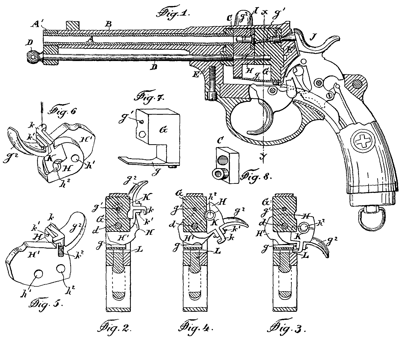
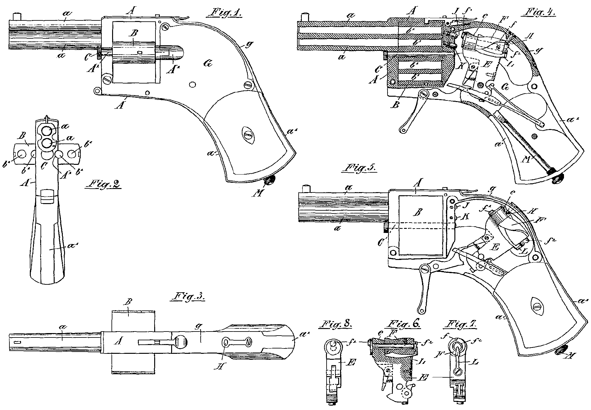
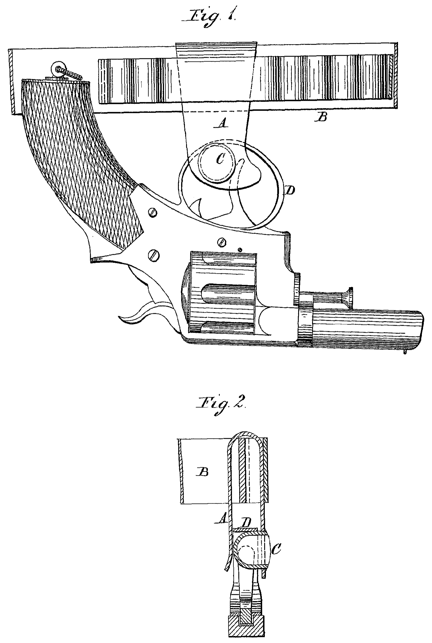
La fig. 1 est une section longitudinale d’un revolver, construit de manière à fonctionner à la main; la forme et les dimensions sont à peu près celles des revolvers ordinaires.
A est le canon, monté en a sur le corps de revolver B et fermé en C de la manière ordinaire. D estjle barillet qui contient les cartouches et qui est capable de tourner sur son axe par les moyens employés dans les autres revolvers; E est l’obturateur qui peut coulisser longitudinalement dans une rainure pratiquée à cet effet dans le corps de revolver B, et qui porte dans son intérieur un percuteur F et un ressort à boudin pour celui-ci. Sur le pivot G est monté le levier L dont la partie supérieure L¹ est à deux branches, et permet ainsi à la gâchette H (qui est montée sur le même pirot G) et au verrou Z qui est monté en à de fonctionner librement entre ces deux bran-ches L¹.
L’extrémité L⁴ de ce levier L est engagée avec l’obturateur E et le percuteur F et la partie inférieure L² est d’une forme convenable pour recevoir l’action de deux ou trois doigts pour faire fonctionner l’arme à la main.
J est un ressort à fourchette monté dans l’intérieur de la poignée B. La branche J¹ est reliée au levier L en L³ par le moyen de la pièce K et tend à pousser la partie L² continuellement en dehors; la branche J est engagée avec la queue du verrou I et tend à le dégager de l’épaule de l’obturateur E. M est la détente qui pivote en m et qui reçoit le mouvement de le gâchette H par lé moyen de la petite bielle N. O et P sont respectivement les ressorts de détente et de gachette.
La gâchette H est pourvue d’une épaule Q, qui sert à faire monter le verrou J et à fermer complètement l’obturateur E (dans la position montrée dans la fig. 1) avant que la gâchette touche l’extrémité de la petite bielle N qui fait fonctionner la détente et dégage le percu-teur. À est le pivot (de la forme particulière montrée dans la fig. 1) de la manivelle S qui se trouve sur le côté du revolver, et peut être tournée à la main dans les deux positions montrées en pointillé dans la fig. 1.
Quand ce pivot R est arrêté par la manivelle dans la position S, la détente M et le verrou I peuvent fonctionner librement, mais si la manivelle est tournée dans la position S¹, la détente M, le verrou I, l’obturateur E et le levier L sont immédiatement rendus immobiles et toute décharge accidentelle est rendue impossible.
T’est le cliquet qui sert à faire tourner le barillet D de la manière ordinaire, après chaque décharge.
U’est une pièce appartenant au corps de revolver B et qui sert à relier les deux côtés de celui-ci et à résister au recul de l’obturateur E sur la tête I¹ du verrou I, au moment de la décharge.
L’arme ainsi construite, fonctionne de la manière suivante:
Si l’on suppose le revolver tenu de la main droite, avec l’index relevé, la gâthette poussée par son ressort P, sera dans la position H¹ indiquée en pointillé (fig. 1).
L’épaule Q qui ne soutient plus le verrou I, laisse cette pièce libre de dégager l’obturateur E par le moyen du ressort J.
Si, maintenant, on ouvre légèrement les doigts qui avaient serré le levier L², la branche J¹ forcera le levier L à tourner sur son axe pour armer le percuteur et extraire la douille de la chambre du canon. Pendant ce même mouvement et aussitôt que la douille est complètement extraite, le cliquet T qui est monté sur le levier L fera tourner le barillet D sur son axe de la quantité nécessaire pour porter une nouvelle cartourehe en ligne avec l’axe de l’obturateur E.
En serrant la main, le levier L sera forcé de reprendre la position montrée dans la fig. 1, en même temps le percuteur sera complètement armé et la nouvelle cartouche poussée par l’obturateur E dans la chambre du canon, de la quantité voulue.
La fermeture de l’obturateur est effectuée par le déplacement de la gâchette (de la position en pointillé H¹ à celle en noir H), qui par le moyen de son épaule Q fait monter le verrou dans la position montrée en fig. 1.
Le mouvement ultérieur de la gâchette sert à faire tourner la détente sur son axe (par le moyen de la petite bielle N) et à dégager le percuteur pour frapper la cartouche, Il est évident que toutes les cartouches contenues dans le barillet D peuvent être tirées par le simple mouvement d’ouverture et fermeture de la main avant de tirer la gâchette H.
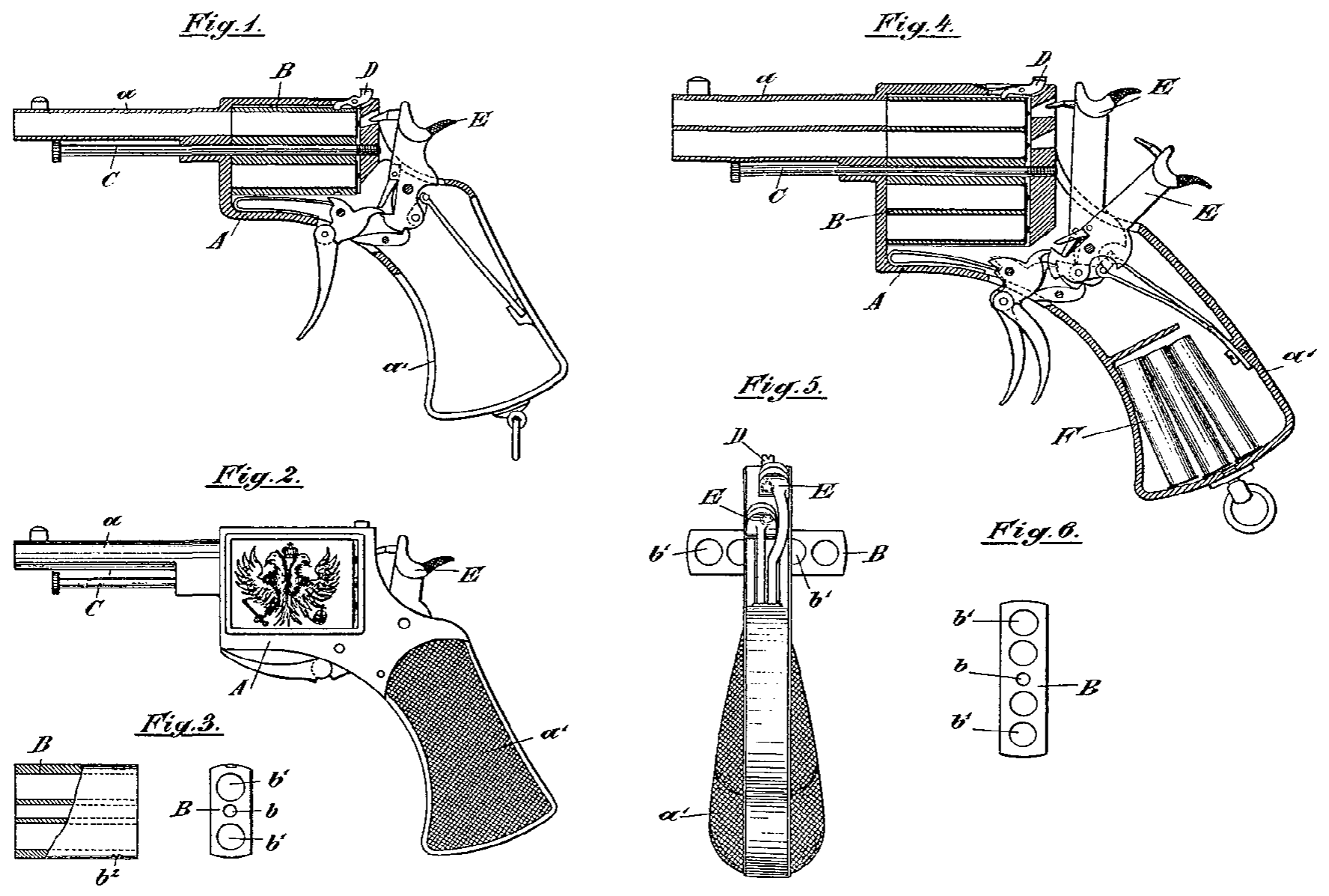
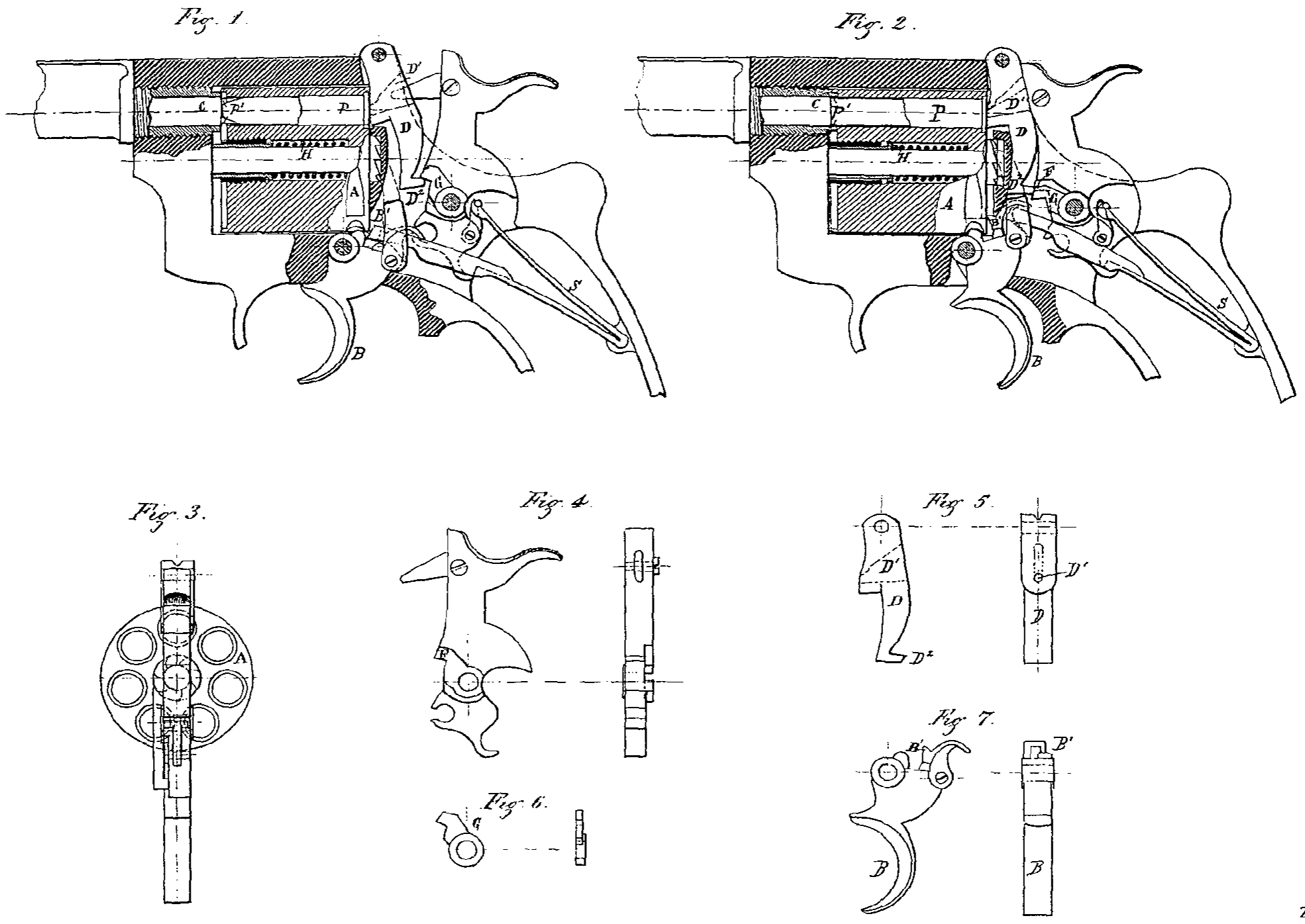
Le revolver montré dans la fig. 2 est le même en principe et disposition générale que celui montré dans la fig. 1, avec la seule différence qu’au lieu de la gâchette H, fig. 1, manœuvrée par l’index, j’emploie la gâchette X, fig. 2, manœuvrée par le pouce.
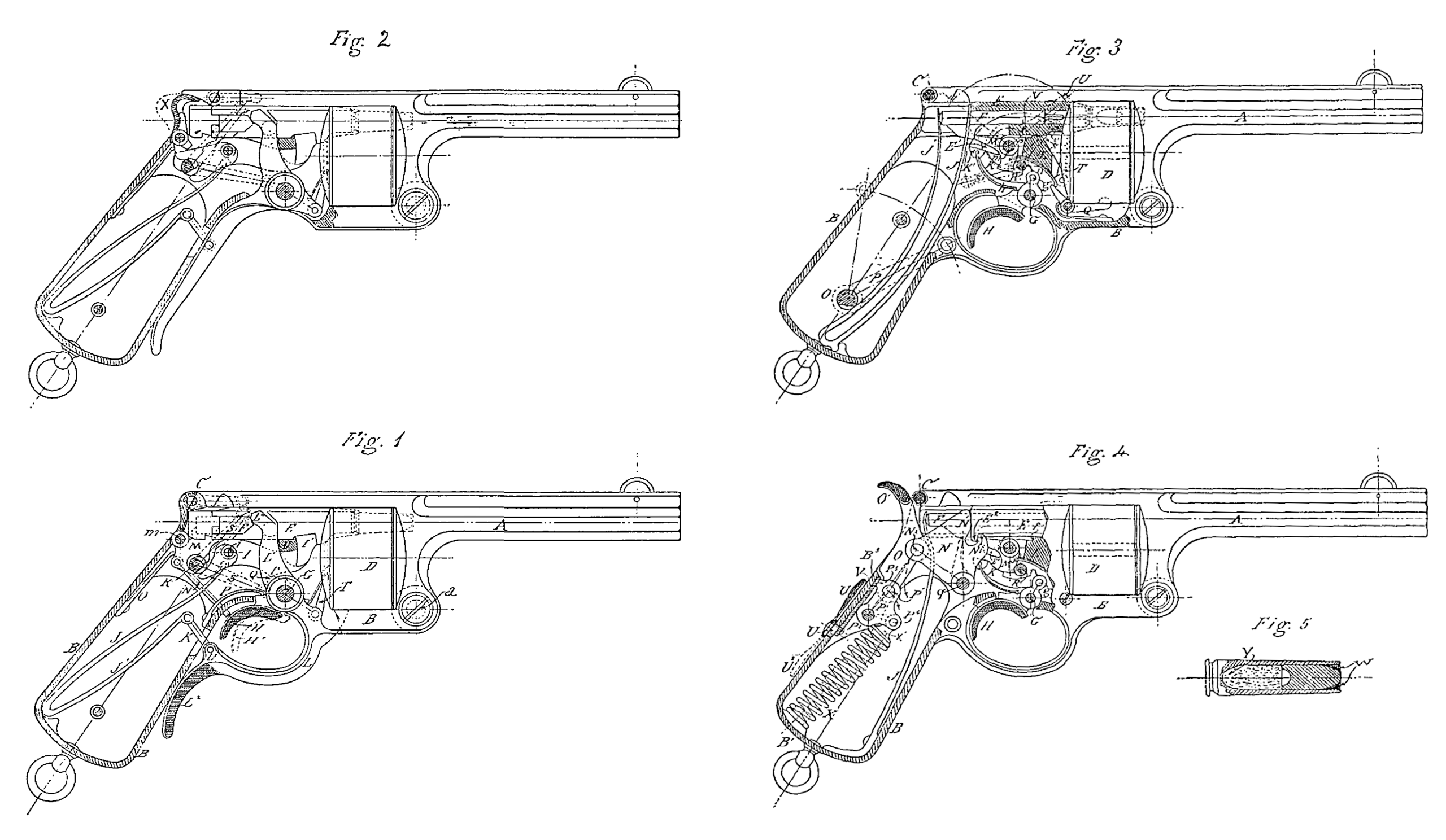
Le revolrer montré par les fig. 1 et 2 ne fonctionne que par les mouvements de la main indiqués plus haut; mais le mécanisme de cette arme peut être disposé de manière que tous les mouvements pour arimer le percuteur, extraire la douille et pousser une nouvelle cartouche dans la chambre du canon, sont exécutés automatiquement par la pression des gaz (au moment de l’explosion) sur la partie antérieure de l’obturateur. Les fig, 3 et 4 représentent deux formes d’exécution de mon invention avec fonctionnement automatique. L’arrangement général du mécanisme pour pousser les cartouches du barillet dans la chambre du canon reste le même que celui de la fg. 1, avec la différence que Le levier L et le verrou I, fig. 1, sont supprimés, et qu’un mécanisme spécial est employé pour empêcher de tirer plus d’un coup à la fois avant que le doigt ne soit relevé de la gâchette.
Dans la fig. 8, A estle canon,B le corps de revolver, D le barillet, E l’obturateur, F le percuteur, J un ressort à fourchette, dont une branche J fait fonctionner l’obturateur et l’autre J¹ le percuteur, et les deux branches ensemble servent à résister à la pression des gaz sur l’obturateur au moment de l’explosion.
L est un levier (qui porte à son extrémité un cliquet T’ pour faire tourner le barillet D) pivoté en m aussi bien que la détente M.
Le mécanisme (qui empêche de tirer un second coup, avant que le doigt n’ai été relevé de la gâchette) comprend la gâchette H (pivotée en G) et le poussoir K (pivoté en g sur la gâchette) dont l’extrémité K est tenue en contact avec l’épaule E¹ de l’obturateur E par le moyen du ressort h, qui est arrangé de manière à faire fonctionner la gâchette et le poussoir indépendamment l’un de l’autre. R est un pivot de la forme montrée dans le dessin, monté sur la manivelle S (qui se trouve sur le côté du revolver) et qui est destinée comme auparavant à rendre la détente M immobile et à prévenir tout accident. Q est le cliquet employé ordinairement pour arrêter le barillet D et O un pivot (solidaire du levier P) qui sert à réduire la tension du ressort J, quand il ne doit pas fonctionner.
U est un levier disposé sur le côté du revolver et monté sur le pivot m2; il est pourvu d’un tenon Y, qui s’engage avec l’obturateur E et sert à charger l’arme et à la faire fonctionner à la main.
L’arme ainsi construite fonctionne de la manière suivante:
Lorsqu’on tire sur la gâchette A, le poussoir K fait pivoter la détente M qui dégage le pereuteur F et la cartouche est frappée.
La pression des gaz (développés par l’explosion de la poudre) pousse l’obturateur E et le percuteur F en arrière contre Le ressort à deux branches J et J¹.
Ce premier mouvement enlève la douille de la chambre du canon, arme le percuteur F dans la position montrée par la fig. 3, et l’épaule ET (de l’obturateur Æ dégage le poussoir K de la détente M, comme il est montré dans la fig. 4.
En examinant cette figure, on voit qu’on ne pourra plus faire feu tant qu’on n’aura pas relevé le doigt de la gâchette A, afin que le poussoir À puisse s’engager de nouveau avec la détente M, comme il est montré dans la fig. 3.
Au lieu d’utiliser l’épaulement E¹ pour dégager le poussoir K de la détente M, le mécanisme peut être disposé de manière que le poussoir K soit tenu dégagé de la détente M par le moyen d’un ressort, et l’épaulement E¹ (ou autre pièce du mécanisme) est employé pour engager ce même poussoir avec la détente M après chaque coup tiré, et aussitôt qu’une nouvelle cartouche est poussée dans la chambre du canon.
Aussitôt que l’arrière mouvement de l’obturateur E contre le ressort J est complété, la branche J qui a été tendue le repousse dans la position montrée par la fig. 3.
Pendant ce mouvement de l’obturateur en avant, l’épaule f du levier L qui avait été poussée en haut par le ressort n vient à buter contre l’épaule e de l’obturateur E qui force ce levier et le cliquet T à descendre, et le barillet D à tourner sur son axe.
Ce mouvement rotatoire du barillet D fait glisser la douille hors de l’obturateur, et monter une nouvelle cartouche en ligne avec le même, qui en complétant son mouvement en avant la pousse dans la chambre du canon, et l’arme est ainsi prête à faire feu.
Il est évident que de cette manière toutes les cartonches contenues dans le barillet D peuvent être tirées en comprimant la gâchette et en relevant le doigt de ladite gâchette, à chaque coup.
Les deux branches du ressort J sont toujours assez résistantes de manière à permettre au projectile de sortir du canon avant que la douille ne soit complètement extraite.
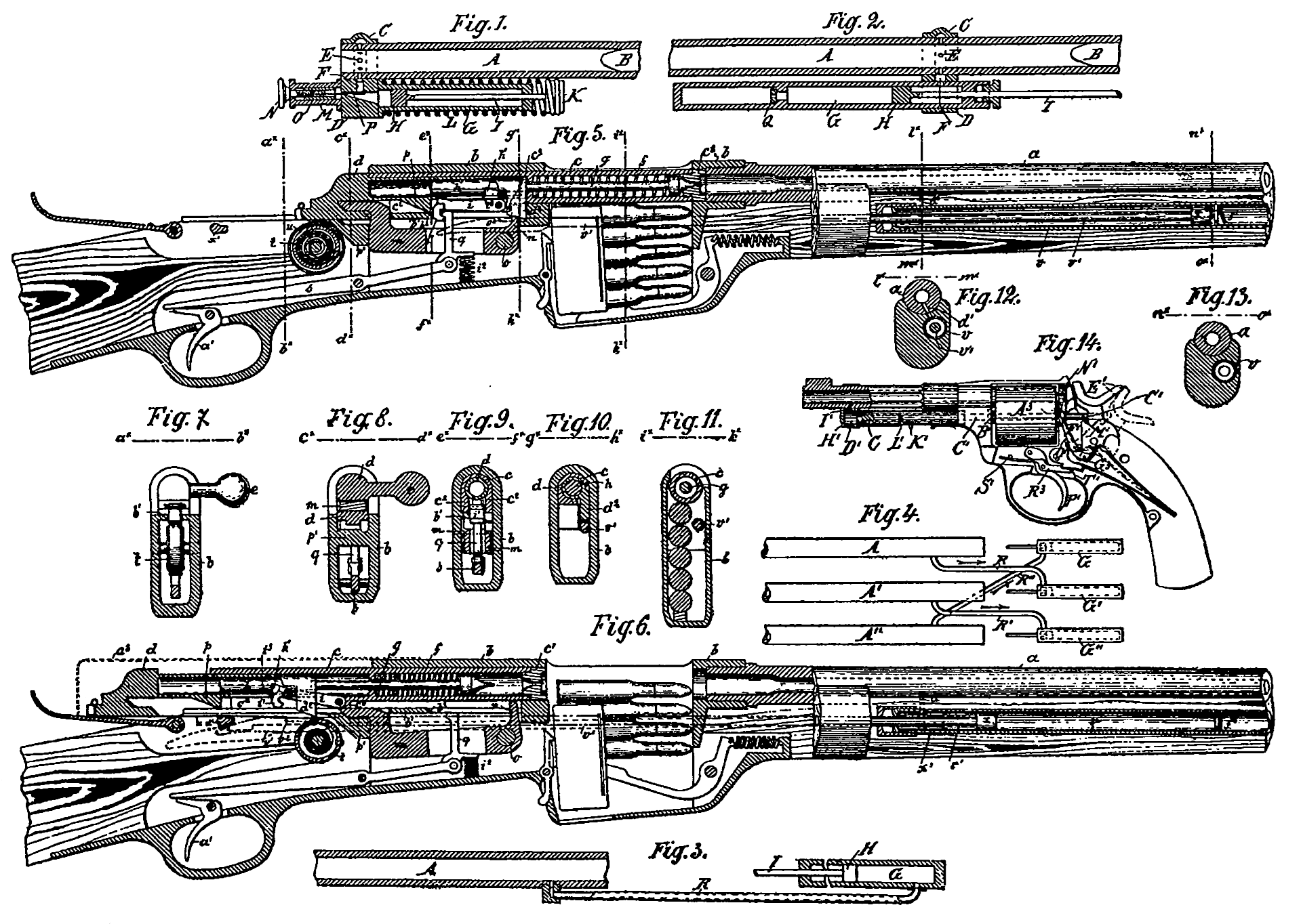
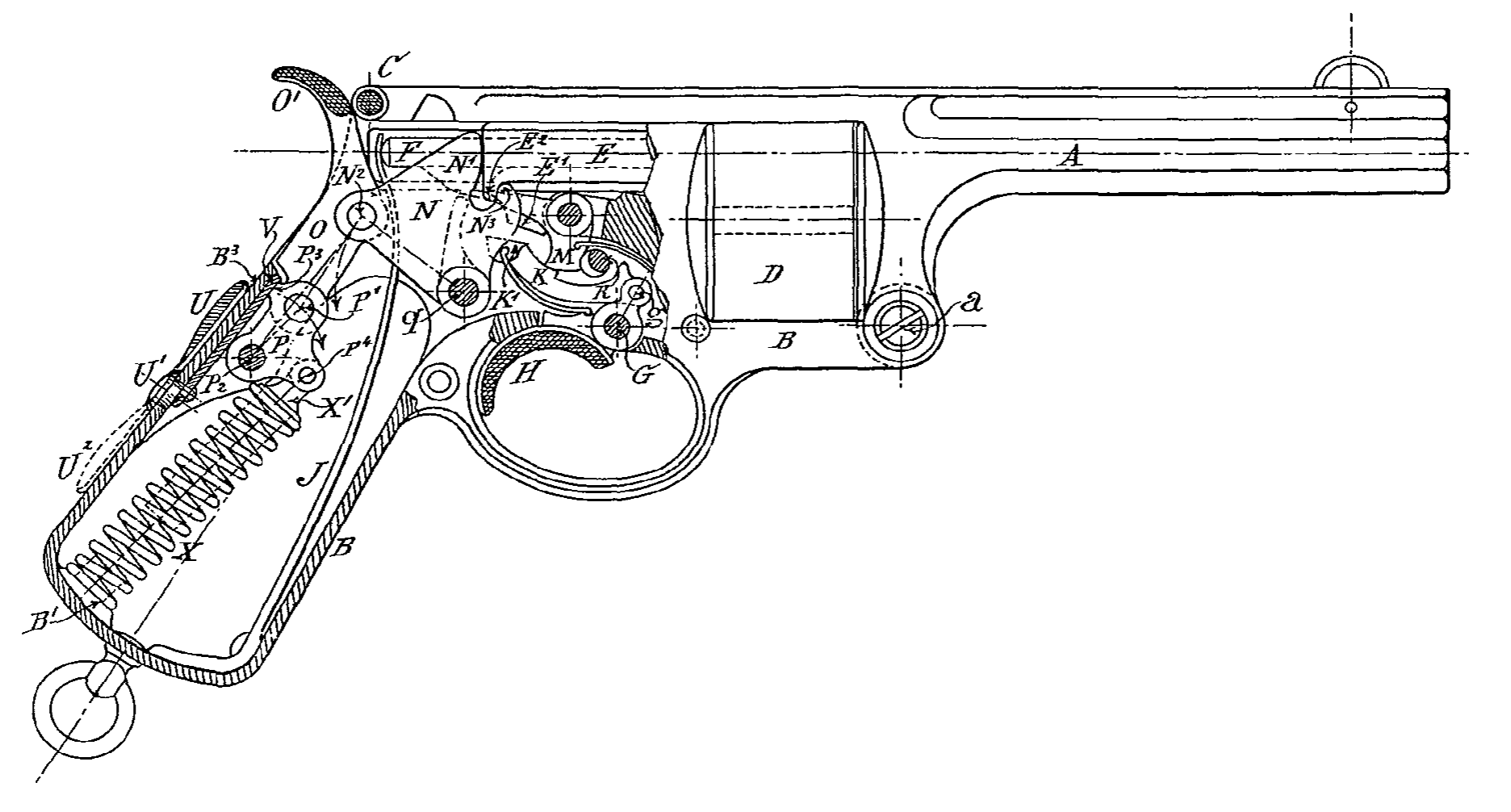
Le revolver représenté en fig. 4 est arrangé de manière à pouvoir fonctionner (indépendamment) automatiquement où à la main.
La construction générale est celle montrée par la fig. 3, avec la différence que le mouve-ment en arrière de l’obturateur E, au lieu d’être limité par le ressort à deux branches J, l’est par un simple ressort (qui fait fonctionner le percuteur) combiné avec un système de trois pièces articulées et gouvernées par un ressort à boudin, comme il est montré dans la fig. 4.
N est la pièce de résistance pivotée en q (sur le corps de revolver) et pourvue d’un passage ou canxelure dans laquelle le ressort J peut fonctionner librement sur le percuteur F.
Le joint O est articulé en N² sur la pièce N et en P¹ sur l’autre joint P, qui à son tour est pivoté en P² sur le corps de revolver.
X est un ressortà boudin, attaché en P⁴ au joint P par le moyen de la tige X¹ et s’appuyant à l’autre bout sur le corps de revolver en B¹. Le joint O passe à travers le corps de revolver et termine avec une sorte de queuc O¹, qui sert pour manœuvrer l’arme à la main.
P³ est un épaulement (sur le joint P) qui frappe contre la glissière V et sert à arrêter les joints O et P dans la position montrée par la fig. 4, avec le centre P¹ hors de la ligne N² P² quand le revolrer doit fonctionner automati-quement. V est une glissière reliée par un excentrique U² au levier U. Quand ce levier U est tourné dans la position en pointillé, fig. 4, cette glissière est retirée de dessous l’épaule P³, qui au lieu defrapper sur la glissière mêmefrappe çontre le corps de revolver en B³, et le centre P¹ est arrêté sur ou au delà de la ligne N² P².
N³ estun épaulementsurla pièce N, qui sert à tirer en arrière l’obturateur E quand le revolver est manœuvré à la main.
L’arme ainsi construite fonctionne de la manière suivante:
Quand le revolver doit fonctionner automatiquement, le lerièr U doit être tourné en baut, comme il est montré en traits pleins à la fig. 4.
Toutes les pièces de la fig. 4 sont représentées dans la position qu’elles acquièrent après qu’on à tiré un coup, et avant qu’on ait enlevé le doigt de la gâchette.
La pression des gaz pousse en arrière l’obturateur E contre la pièce N et le pereuteur F contre le ressort J.
L’arrière mouvement de l’obturateur D est transmis (par le moyen des pièces N O P) sur le ressort à boudin X et le pivot P² dont l’ef-fort est inversement proportionnel à la quan-tité, dont le centre P1 est hors de la ligne N², P² et la distance P² P⁴.
Ces dimensions varient selon le calibre de l’arme et la qualité de la poudre employée.
L’arrière mourement de lobturateur E fait tourner la pièce N sur son pivot g et les joints O et P tournent aussi avec leur centre P¹ dans la direction de la flèche, de manière à comprimer le ressort à boudin et à armer le percuteur dans la position montrée par la fig. 4.
Aussitôt que la force de l’explosion est complètement épuisée, le ressort à boudin X qui avait été comprimé, poussera immédiatement toutes les pièces dans leur position respective, comme il est montré par la fig. 4.
La rotation du barillet D, l’action de l’obturateur sur les cartouches dans la chambre du canon et le mécanisme pour tirer coup sur coup restent, comme cela a été expliqué plus haut en regard de la fig. 3.
Dans ce cas aussi, toutes Îes cartouches contenues dans le barillet D peuvent être tirées, en comprimant et en relevant le doigt de la gâchette alternativement à chaque coup.
Si, au lieu de le faire fonctionner automatiquement, l’on entend manœuvrer ce revolver à la main à chaque coup, le levier U doit être tourné dans la position montrée en pointillé dans la fig. 4.
Ce mouvement retire la glissière V de dessous l’épaulement P³, et les joints O et P poussès par le ressort à boudin X sont arrêtés alors avec leur centre P¹ sur (ou au delà de) la ligne N² P².
Dans ce cas, l’effort total de l’explosion est supporté par le pivot P², et toutes les pièces E N O et P sont rendues imnnobiles.
Pour tirer chaque cartouche contenue dans le barillet, le seul mouvement nécessaire est de comprimer avec le pouce la queue O¹ du joint O de la même manière que l’on arme le chien d’un pistolet.
Ce mouvement arme le percuteur et tire la douille dé la chambre du canon.
Le mouvement opposé (effectuë par le ressort à boudin X) fera tourner le barillet D et amèênera une nouvelle cartouche en face de lobturateur qui la poussera aussitôt dans la chambre du canon.
L’arme est ainsi prête à faire feu en comprimant la gâchette.
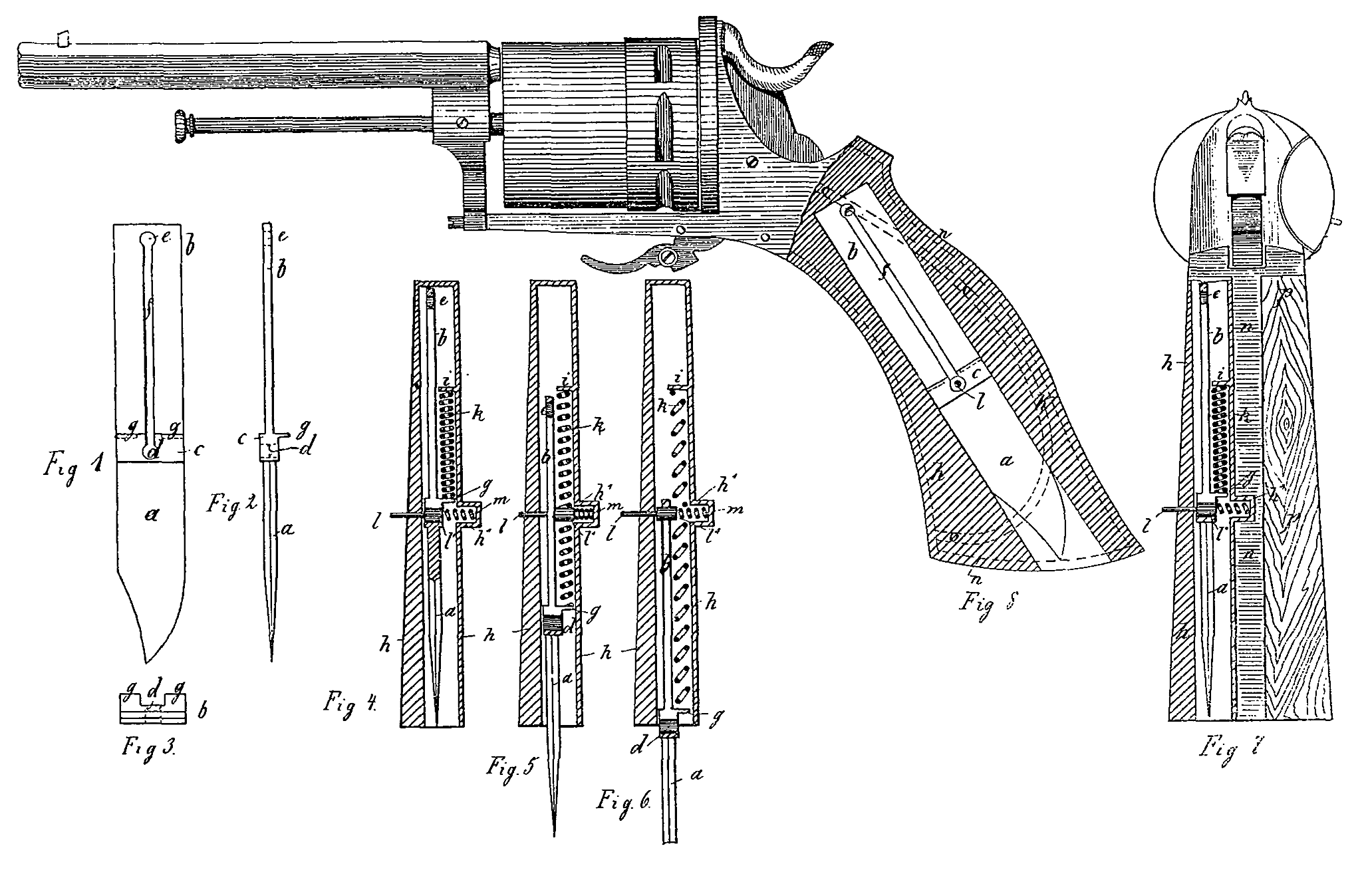
Les cartouches que j’emploie généralement pour ma nouvelle arme à feu sont montrées, à plus grande échelle, par la fig. 5.
Elles sont légèrement coniques, avee la douille prolongée à l’extrémité du projectile, etavec le culot Y’d’une forme ovoïdale, et assez épais, afin qu’elle puisse résister arec sûreté à la pression des gaz, dans les cas où l’extraction commence an moment même de l’explosion et du déplacement du projectile.
La partie W est remplie de cire, graisse ou autre matière lubrifiante.
REVENDICATIONS:
1º Arme à feu avec barillet, caractérisée par un mécanisme destiné à pousser chaque cartouche d’une certaine quantité dans la chambre du canon, de manière que la douille puisse complètement fermer le passsge entre le barillet et le canon, afin d’éviter toute fuite de gaz, constitué par un obfurateur disposé dans l’axe géométrique du canon, susceptible d’un mouvement alternatif et disposé pour pousser chaque cartouche dans la chambre du canon;
2º Dans une arme à feu, caractérisée par la revendication 1, l’obturateur disposé de manière à pouvoir être repoussé par l’ac-tion des gaz d’explosion et avancé par l’action d’un ressort;
3º Dans une arme à feu, caractérisée par la revendication 1, l’ohturateur pourvu d’un épaulement à sa partie inférieure et un levier monté sur l’axe de la détente et pourvu d’un épaulement correspondant et d’un eliquet, de sorte que l’obturateur dans son avant-course puisse faire descendre ledit levier poussé en haut par un ressort et faire tourner le barillet d’un angle déterminé;
4º Dans une arme à feu, caractérisée par la revendication 1, un pivot monté sur une manivelle et destiné à rendre immobile la détente et à prévenir tout accident;
5º Dans une arme à feu, caractérisée par la revendication 1, un mécanisme pour empêcher de tirer plus d’un coup à la fois avant de relever le doigt de la gâchette, consistant dans la gâchette (M, fig. 3 et 4) pourvue d’un poussoir (K) destiné à engager la détente (M) par l’action d’un ressort (h) et à être automatiquement dégagé de la même à l’aide d’un épaulement (E¹) de lobturateur après chaque coup;
6º Dans une arme à feu, caractérisée par la revendication 1, un système de leviers (N O P, fig. 4) entre l’obtarateur (E) et le ressort (X) pour l’avant-course de celui-ci, disposé de manière que le recul de l’obturateur puisse être opéré suivant le désir par l’action des gaz d’explosion ou par la mise en action du levier (O) au moyen de sa queue (O¹);
7º Dans une arme à feu, caractérisée par la revendication 1, une glissière (V, fig. 4) avec levier (U) et excentrique (U¹) pour arrêter les leviers (O P) avec leur centre commun (P¹) au-dessus ou au-dessous de la ligne centrale (N² P²) suivant que l’on veut le recul à la main ou automatique de l’obturateur (E).
Colombo RICCI.
Mandataire: BOURRY-SÉQUIN, à ZURICH.