Germany 2564
PATENTSCHRIFT
1878 — Nº 2564 — Lasse 72
PAUL MAUSER in OBERNDORF (Württenberg).
Neuerungen an Revolvern.
Patentirt im Deutschen Reiche vom 2. März 1878 ab.
Die Erfindung betrifft emen Revolver oder eine Drehpistole von einer von den bisherigen Systemen wesentlich abweichenden Construction. Das Umschalten der Walze geschieht bei diesem Revolver wie bei den neueren amerikanischen während des Aufziehens oder Spannens des Hahnes. Der Hahn wird nämlich vor jedem Schufs mit dem Daumen gespannt. Allerdings hat dies eine etwas geringere Schnelligkeit des Feuerns zur Folge, was aber durch die viel gröfsere Sicherheit des Schusses aufgehoben wird. Letztere übertrifft die des amerikanischen auch bedeutend dadurch, dafs mit meinem Re-volver von Kaliber ro mm ein Geschofs von 14 g Gewicht mit 1,7 g Pulverladung geschossen wird.
Hauptvorzüge des neuen Revolvers sind nachstehende: Der Umschalter oder Transporteur greift nicht an der Stirnfläche der Walze an, wie bei dem amerikanischen, sondern an dem Umfange derselben. Hierdurch wird der wirksame Hebelarm bedeutend verlängert und das Aufziehen des Hahnes erleichtert. Diese Anordnung hat bei gröfserer Sicherheit auch noch zur Folge, dafs austretende Pulvergase nicht in das Innere des Schlofsgehäuses gelangen können, weil eben der Mechanismus zum Umschalten der Walze von der Stiim nach dem Umfang derselben verlegt wird und die Schlufsplatte keinerlei Oeffnungen besitzt, welche ins Innere des Schlofsgehäuses führen. Der neue Revolver zeichnet sich ferner noch dadurch aus, dafs sein Mechanismus ein aufserordentlich einfacher ist; er besitzt im ganzen nur 33 Theile, während amerikanische bisweilen aus 56 Theilen zusammengesetzt sind.. Infolge dessen ist derselbe sehr leicht auseinander zu nehmen. Um ihn zu reinigen, bedarf es in der That nur der Lösung einer einzigen Schraube, man kann dann sämmtliche Theile mit der Hand ausemandernehmen, reinigen und einölen.
Eine weitere Eigenthümlichkeit besteht m der neuen Construction des Ausziehers der Patronenhülsen.
Auf beiliegender Zeichnung ist:
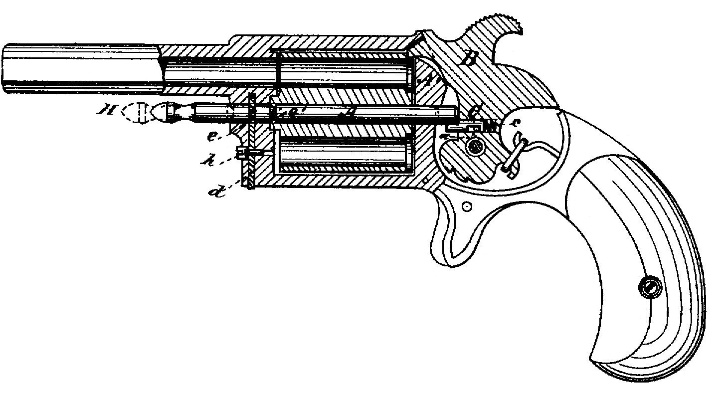
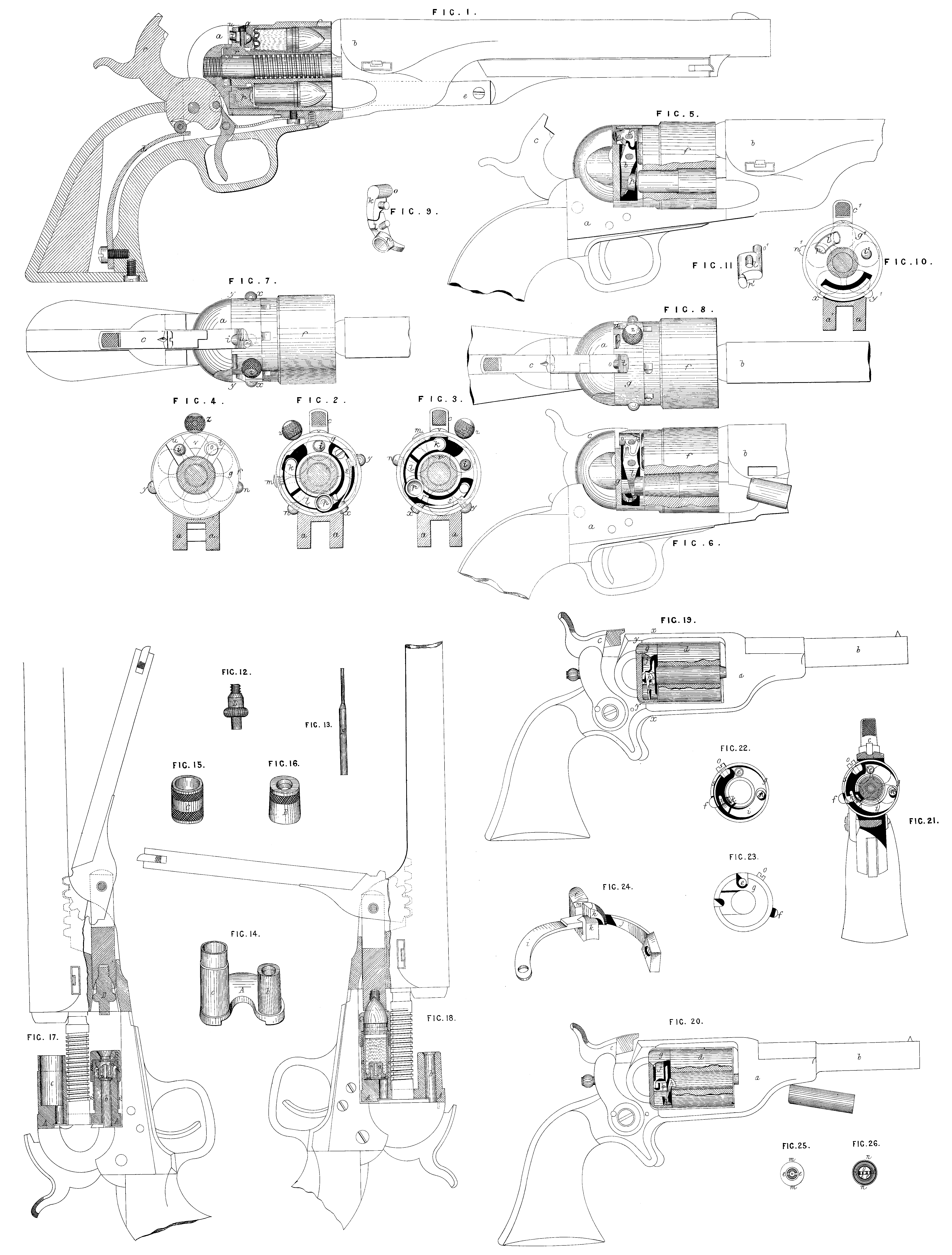
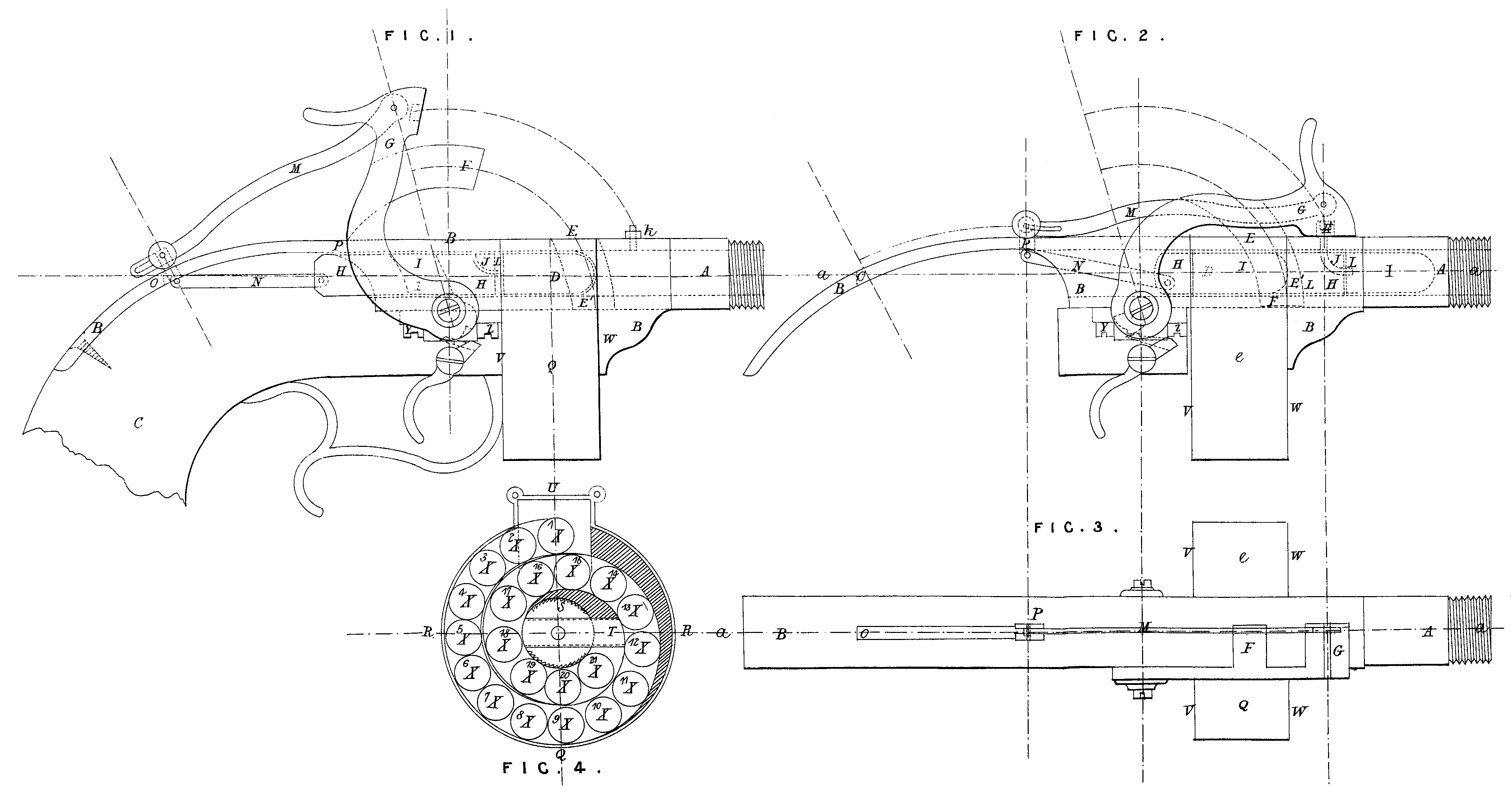
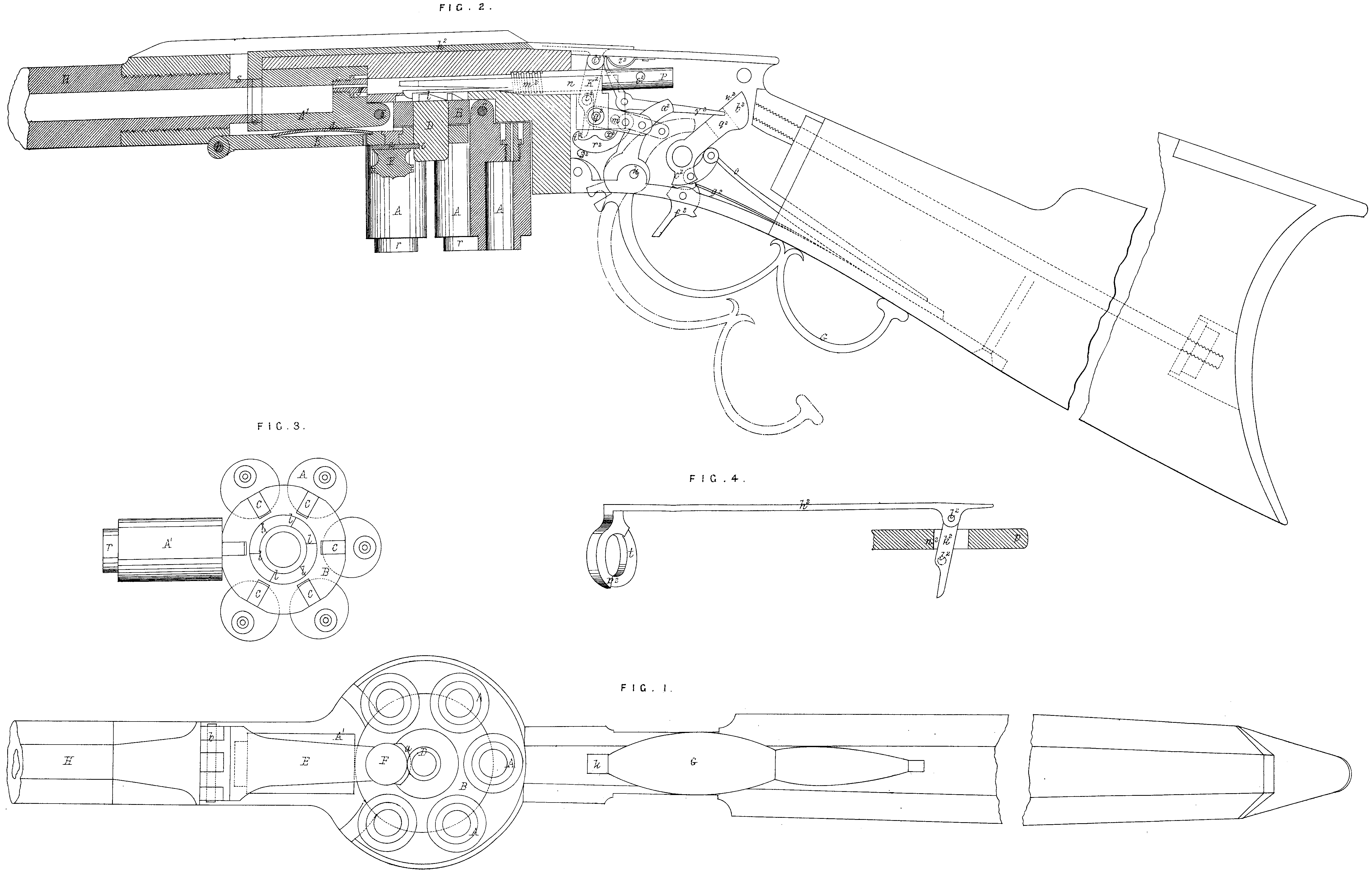
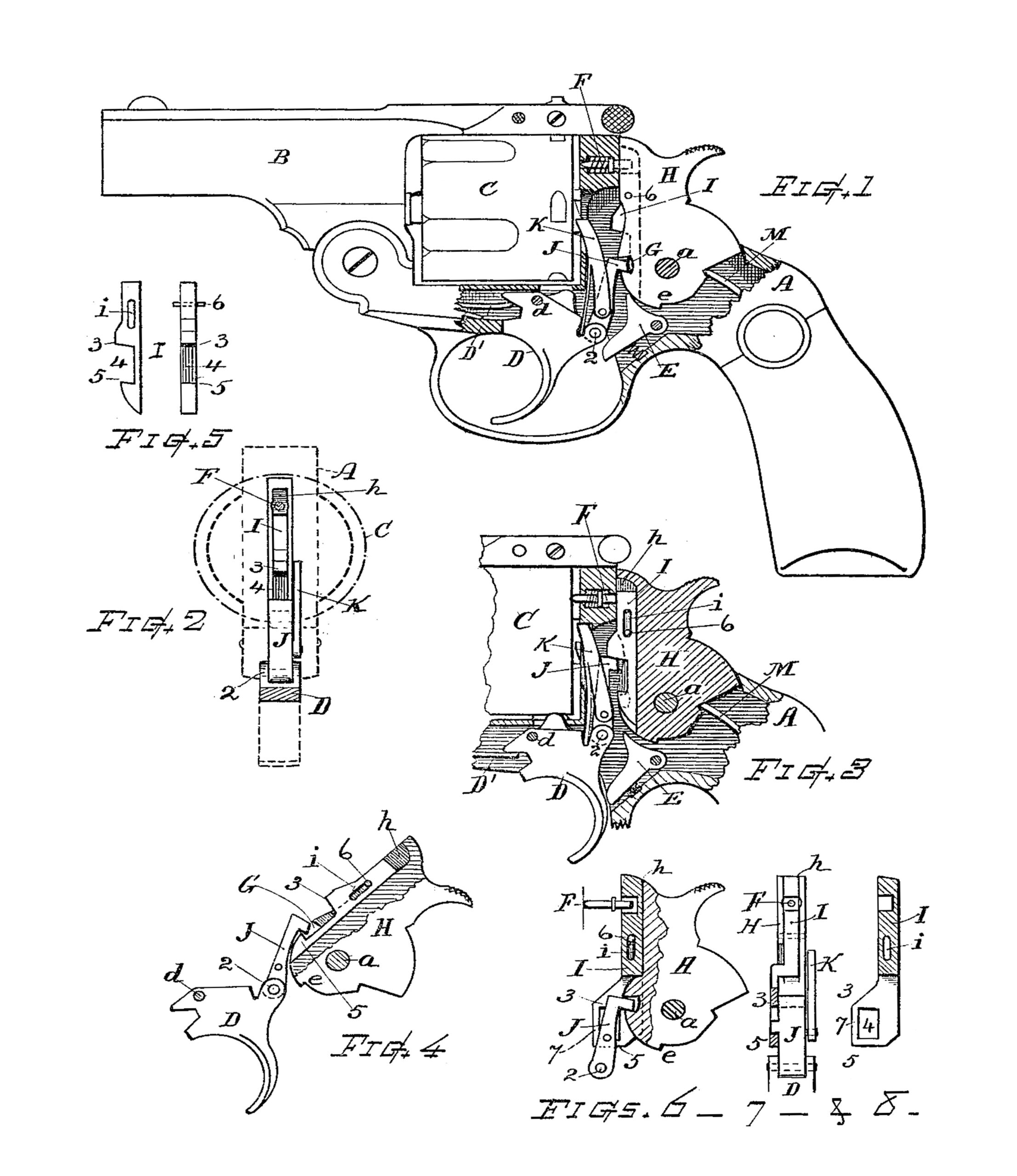
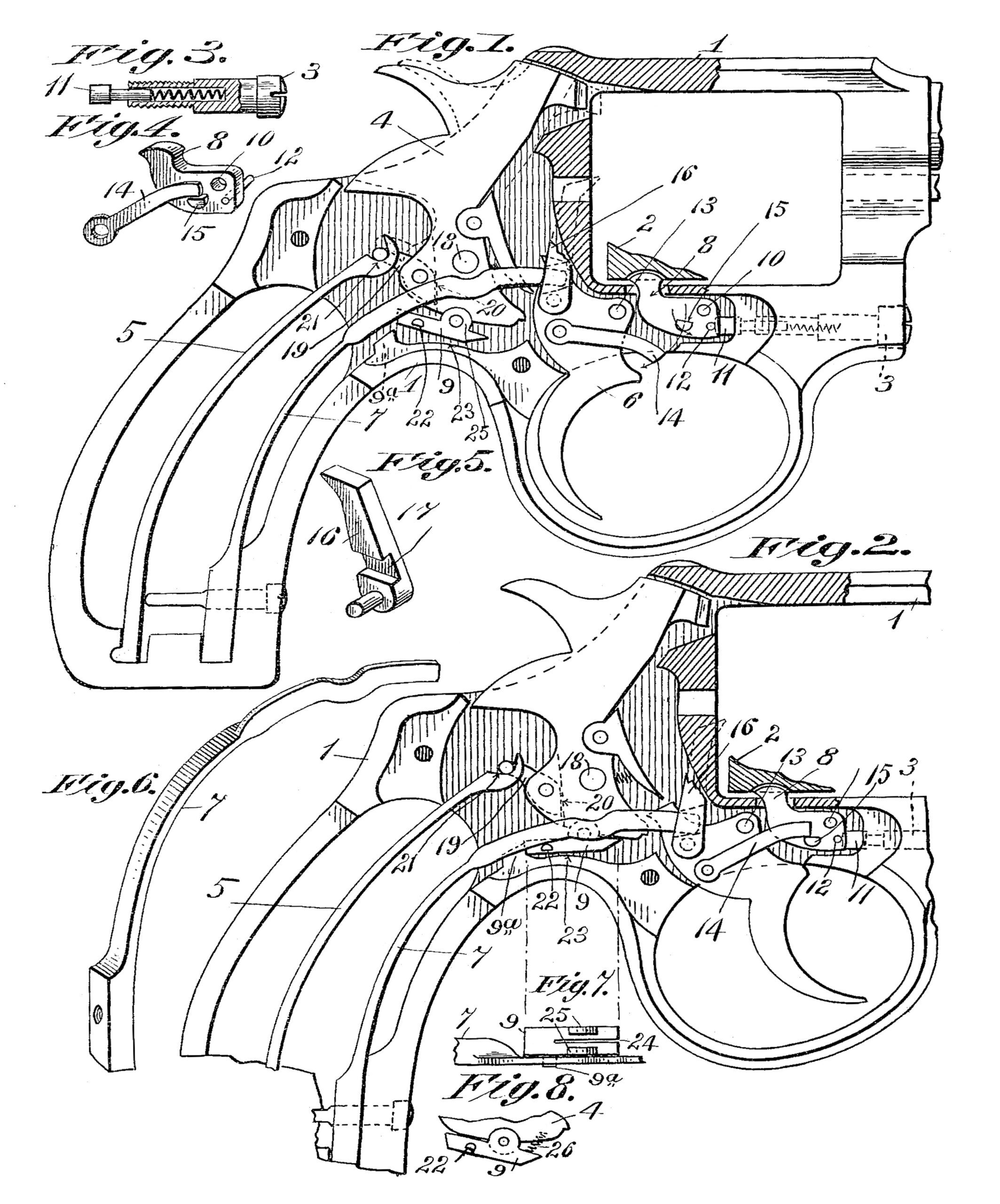
Fig. 1 ein Durchschnitt durch die Seelenaxe und zeigt den ganzen inneren Mechanismus des Revolvers.
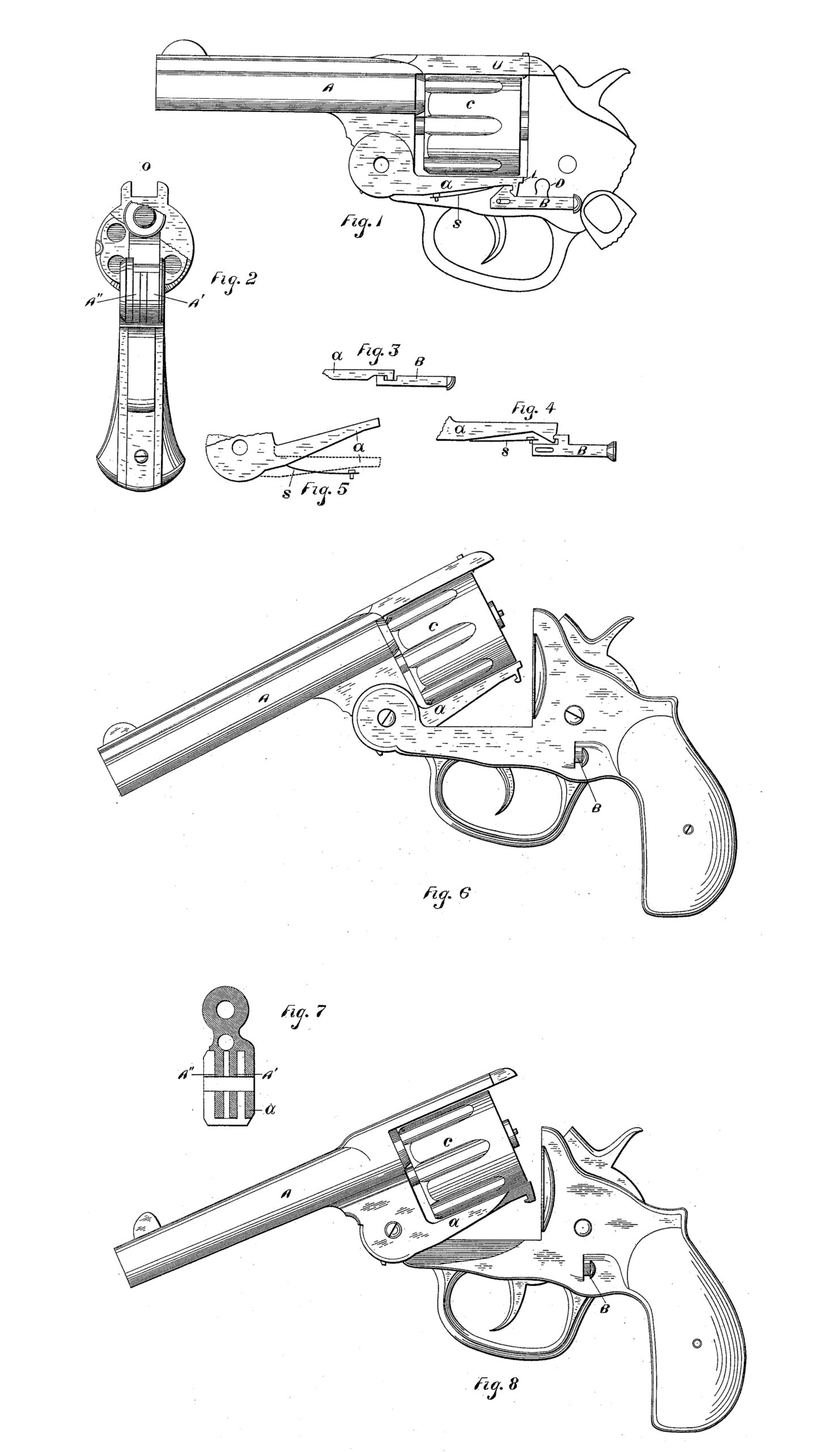
Fig. 2 ist eine äufsere Ansicht desselben.
Fig. 3 ist ein Querschnitt nach der Linie A B.
Fig. 4 eine äufscre Ansicht der Walze und zeigt namentlich die auf dem Umfange derselben eingefrästen Nuthen, in welche der Umschalter oder Transporteur eingreift.
Fig. 5 ist ein Querschnitt nach der Linie C-D bezw. Ansicht von der Mündung her.
Fig. 6 Querschnitt. des Schaftes und die Befestigung der Holzbacken.
Fig. 7 Ansicht des Revolvers von hinten.
Fig. 3 mehrere Ansichten des Schlagbolzens und des Hahnes.
Fig. 9 eine Ansicht des Bügels von oben nach Abnahme desselben vom Gehäuse.
Fig. 10 Ansicht der Versicherung von der Seite.
Fig. 11 drei Ansichten des Auswerfers der Patronenhülsen.
Fig. 12 vordere Stirnfläche der Walze.
Fig. 13 hintere Stirnfläche derselben.
Die Haupttheile sind in der Zeichnung mit den grofsen Buchstaben des Alphabetes bezeichnet, während die Bestandtheile dieser Hauptkörper durch den gleichen kleinen Buchstaben mit Beisetzung einer Zahl benannt werden.
I I¹ ist der Hauptkörper oder das Gehäuse des Revolvers. Es besteht aus den beiden Theilen I I¹, welche mittelst eines Scharniers i vereinigt sind und bei i¹ sich öffnen lassen.
K ist der Lauf, L die Walze, M der Bügel, N der Schlagbolzen, O der Hahn, P die Sicherung. Das Gehäuse I I¹ ist aus Eisen oder Stahl mit ebenen Seitenwänden. Dasselbe ist im Innern ausgefräst, um das Schlofs aufzunehmen. Der vordere Theil i² ist etwas verdickt und besitzt das Gewinde, worin der Lauf eingeschraubt ist. Hinter der Walze verbreitert sich das Gehäuse zu einer runden, sogenannten Stoßsplatte i³. Der hinterste Theil ist gänzlich ausgehöhlt und bildet nur einen leichten Rahmen i⁴, Fig. 1 und 6, der von zwei Seiten durch den Holzschaft i⁵ geschlossen wird. Eine einzige Schraube i⁶ genügt, den Holzschaft an dem Metallrahmen i⁴ zu befestigen. Oben über der Walze ist das Gehäuse I¹ ausgeschnitten, damit so wenig wie möglich Raum gegeben wird, worin sich Schmutz ansetzen könnte, Etwa austretende Pulvergase können dadurch ins Freie entweichen.
Auf dem Scharnier ist das Visir eingestrichen.
Auf dem Rücken des Gehäuses tritt der Hahn hervor, der die ganze Breite der Ausfräsung ausfüllt; seine beiden bogenförmigen Scheiben o¹ und o² schliefsen möglichst dicht an die Gehäusewände an und da sie aus dem gemeinschaftlichen Mittelpunkt o beschrieben sind, so schliefsen sie auch nach diesen zwei Seiten das Gehäuse und verhindern das Eindringen von Schmutz.
Unten ist die Ausfräsung des Gehäuses durch den Bügel M geschlossen. Gegen die Walze hin bietet das Gehäuse nur eine schmale, schlitzförmige Oeffnung i¹¹, durch welche der Umschalter oder Transporteur hervortritt. und darin hin-und herläuft. Gegen Eindringen von Schmutz ist diese Oeffnung durch die Walze selbst geschützt.
Am vorderen Theil, wo der Schlagbolzen N hervortritt, ist. die Oeffnung durch diesen selbst und die Schlagbolzenmutter n⁴ geschlossen.
Der Abzug m füllt die. ganze Oeffnung des Bügels, durch welche er mit dem Innentheil des Schlosses ın Verbindung steht, aus; seine Spitze m², sowie der Theil des Schlagbolzens, worin. die Rasten n⁶ und n⁷ eingefeilt sind, schliefsen den vordersten Theil der Oeffnung. Der hintere Theil derselben m¹ ist durch die Abzugfeder m³ geschlossen.
Um die Patronen oder Patronenhülsen herauszunehmen, kann das Gehäuse einfach dadurch geöffnet werden, dafs man die Sicherung P in der Richtung des Pfeiles in die Höhe schiebt, womit. der schiefe Haken p der Sicherung die Nase i⁷ frei läfst, Die Stellung des Scharniers zu diesem Haken ist, wie Fig. 1 zeigt, eine solche, dafs der Schlufs ein vollkommen genügender ist.
Ueber den Lauf k ist neues nicht zu sagen, derselbe ıst in der gebräuchlichen Weise gebildet und im I¹ eingeschraubt.
Die Walze L dagegen bietet wesentliche Verschiedenheiten gegen andere Revolverwalzen.
Sie besitzt die gewöhnlichen sechs Patronenlager und dreht sich um einen Bolzen l³, den Walzenbolzen; derselbe liegt an einer Seite in der Bohrung i⁸ des Gehäuses I¹, sein konisches Ende l⁴ pafst genau in eine Bohrung mitten in der Stofsplatte i³, Der hintere Theil des Bolzens ist auch deshalb konisch, damit beim Oeffnen und Schliefsen des Gehäuses der Konus l⁴ ohne Schwierigkeit in die Bohrung der Stofsplatte eintreten kann.
Das andere Ende des Walzenbolzens ist mit einer kleinen Kehle l² versehen; in diese greift die Nase einer kleinen Feder k ein, welche, wie Schnitt C D (Fig. 5) zeigt, in einer Nuth k¹ des Laufes liegt und deren rechtwinklig umgebogenes Ende mit dem Lauf gegen den Schraubtheil des Gehäuses I¹ festgeschraubt ist.
Ueber den so festgehaltenen Bolzen l³ ist Kine aus den Theilen l⁶ und l⁷ bestehende Büchse aus Stahl geschoben, der sogen. »Auswerfere«. Deıselbe ist in Fig. 11 in drei Ansichten für sich allein gezeichnet.
Das konische Ende l⁶ pafst in eine konische Böhrung des Gehäuses; den Zwischenraum zwischen dem Gehäuse und der Walze nimmt ein kleiner Ansatz 7 ein. In den konischen Theil sind sechs Einschnitte 1, 2, 3, 4, 5, 6 gemacht, deren Zweck wir später beschreiben werden.
Die beiden Theile des Auswerfers stofsen ın einer schneckenförmigen Schnittlinie zusammen, welche eine Drehung des Theiles l⁷ nur nach einer Richtung gestattet, nach der anderen Richtung ist die Drehung nur bei gleichzeitigem Aufsteigen auf der Schneckenlinie gestattet. Der Theil l⁷ hat eine Flantsche, welche vollständig in die Walze eingelassen ist, so dafs ihre obere Fläche in der hinteren Walzenfläche liegt. Die Flantsche ist so grofs, dafs sie über die Löcher oder die Patronenlager hinausgreift und alsdann sechsmal so ausgeschnitten ist, dafs die Kante dieser Ausschnitte gerade die Patrone berührt, aber unter den Rand derselben untergreift.
Um nun mittelst dieses Auswerfers die Patronen aus der Walze zu entfernen, Öffnet man das Gehäuse, indem man bei P in der Richtung des Pfeiles drückt, wodurch der Haken p die Nase l⁷ frei läfst, zugleich aber auch der Stift p¹ mit seinem flachgefeilten Ende in einen der Einschnitte 1, 2….6 eintritt. Der Vordertheil des Auswerfers ist mit einem feststehenden Keil versehen, der sich in einer Nuth der Walze dreht. ‚Wenn daher der Stift p¹ in einem der Einschnitte durch Druck auf die Sicherung p¹ festgehalten wird, so läfst sich die Walze L nur nach einer Richtung drehen, nämlich nach der, bei welcher der Theil l⁷ auf der Schneckenlinie von l⁶ hinaufsteigt. Die gerade Endfläche der schiefen Fläche verhindert die Drehung nach der entgegengesetzten Richtung. Bei dem Hinaufsteigen des Auswerfers tritt dieser aus der Walze heraus und da er die Ränder der Patrone unterfafst, so nimmt er dieselben so weit mit heraus, dafs sie zusammen in die Hand fallen.
Die um den Bolzen gewundene Spiralfeder l⁸, welche beim Vortreten des Auswerfers gespannt wird, bewirkt auch wieder das Zurücktreten desselben.
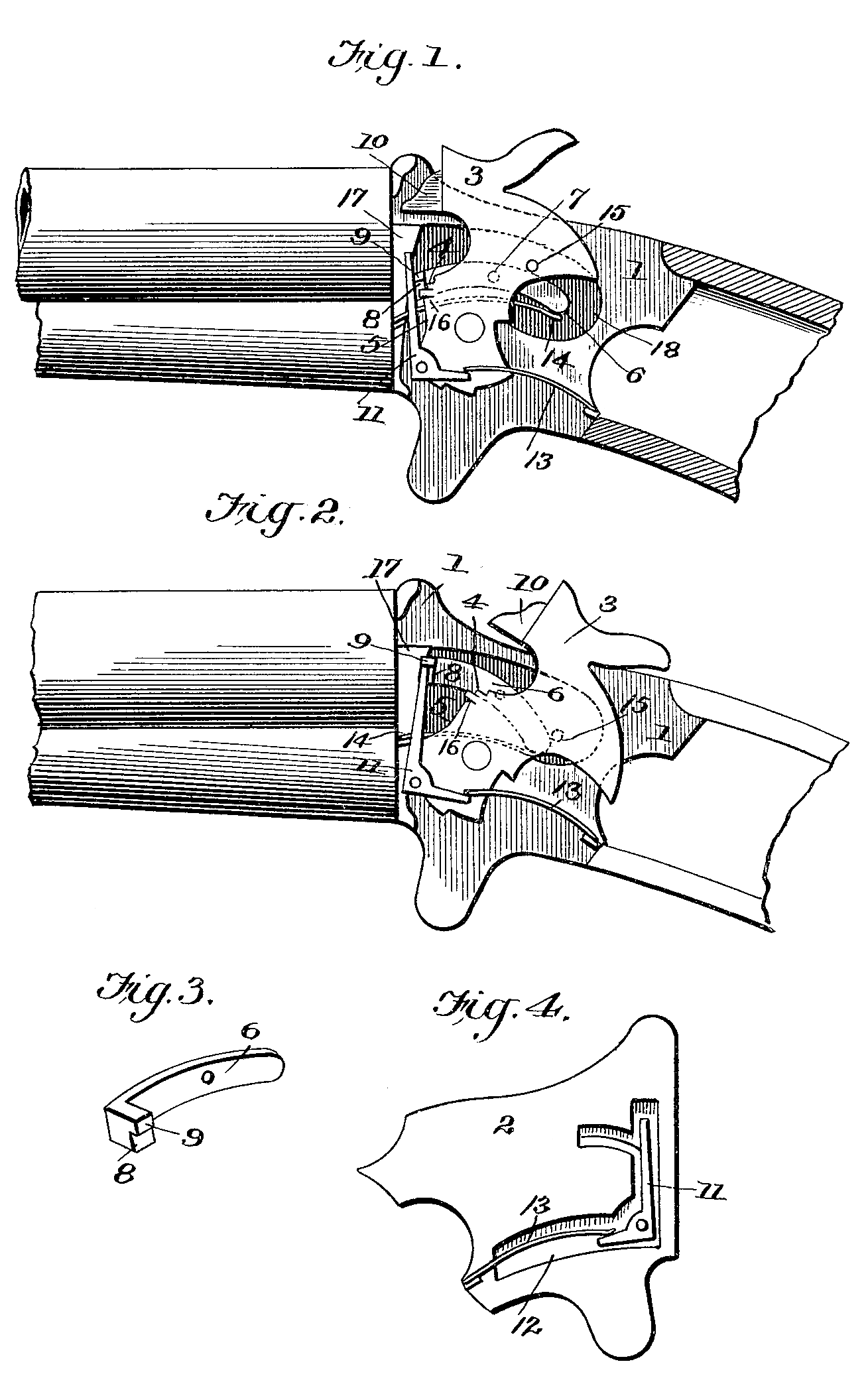
Am äufseren Umfange ist die Walze L mit den Nuthen l l¹ versehen, welche. im Zickzack um sie herumlaufen. Die Nuthen l sind parallel der Erzeugungslinie der Walzenoberfläche, die schiefen Nuthen verbinden immer die entgegengesetzten Enden zweier benachbarten geraden Nuthen. Die Bodenfläche der geraden Nuthen steigt von ihrem hinteren Ende bis zu ihrem Eintritt in die schiefen Nuthen, Fig. 1. In diese Nuthen greift nun der sogenannte »Transporteur« oder Umschalter ein und wird durch das Oeffnen des Hahnes darin verschoben.
Der Umschalter besteht aus einer kleinen Zunge n⁸, welche in einer Ausfräsung des Schlagbolzens um einen kleinen Stift n⁹ beweglich ist. Eine Feder n¹⁰ drückt die Zunge stets so weit aus der Ausfräsung hervor, dafs ihr Ende n¹¹ auf dem Schlagbolzen aufsitzt. Oeffnet man den Hahn O, so wird der Schlagbolzen N von dem gabelförmigen Ende o⁴ des Hahnes vorwärts geschoben. Der mit vorwärts geschobene Transporteur greift mit seinem Knopfe n¹² in die Nuth l¹ ein und zwingt bei seinem geraden Vorwärtsschreiten die Walze sich zu drehen. Am Ende der schiefen Nuth l¹ fällt er in die gerade Nuth L ein und genau gleichzeitig hiermit fährt auch der Abzug m in die Rast n⁷. Beim nun folgenden Los-drücken fährt der Schlagbolzen zurück und der Stift n¹² gleitet in der geraden Nuth l zurück, ohne die geringste Drehung der Walze zu verursachen. Er gleitet dabei auf der aufsteigenden Grundfläche der geraden Nuth hin und fällt dann plötzlich an der Stelle, wo die schiefe Nuth in die gerade einmündet, auf den Grund der ersteren in die Ecke x x, Fig. 4.
Beim folgenden Aufziehen des Hahnes wiederholt sich der Vorgang, so dafs die Walze wiederum um ein Sechstel gedreht und für einen zweiten Schufs gestellt wird.
Beim Spannen des Hahnes wird die Spiralfeder n⁵ zusammengedrückt. Diese liegt gegen die Schlagbolzenmutter n⁴, siehe auch Fig. 8, und an der hinteren Verbreiterung n² des Schlagbolzens.
Der Hahn greift in die Ausschnitte n n ein.
Der Schlagbolzen macht eine genau geradlinige Bewegung, da er vorn in der Schlagbolzenmutter und hinten in den cylindrischen Aushöhlungen vom Durchmesser n¹, Fig. 3, geführt ist.
Die Rast n⁶ ist so gestaltet, dafs der Abzug mit seiner Spitze darin festhält, sobald er einmal eingeschnappt ist. Die Rast n⁷ ist weniger unterfeilt, so dafs der Abzug beim Drucke des Fingers leicht heraustritt und der Schlagbolzen unter der Wirkung der Feder vorfährt. Hiermit wird der Hahn zugeschlagen und fährt mit seiner Spitze in das Zündhütchen und der Schufs geht los.
Der Bügel M ist in folgender Weise an dem Untertheil des Gehäuses befestigt:
Der Haken m⁴ greift um die Ecke i⁹ und der vordere Haken m⁵ fafst in einen Haken der Schlagbolzenmutter n⁴, welche darin durch die Feder n⁵ festgehalten wird. Die Nase m⁶ stemmt sich gegen einen Ansatz i¹⁰ des Gehäuses I.
Diese einfache Befestigung des Bügels entbehrt daher jeder Schraube und kann dadurch gelöst werden, dafs man mit einem hohlschlüsselförmigen Instrument, Fig. 14, n¹⁴ so weit niederdrückt, bis der Haken m⁵ frei wird. Alsdann fällt der Bügel heraus und die Schlagbolzenmutter wird durch die Feder herausgetrieben.
Löst man sodann die Schraube o des Hahnes, so kann dieser herausgenommen werden. Wenn man dann den Stift n¹² des Transporteurs wieder in seinem Schlitz i¹¹ niederdrückt, so läfst sich der Schlagbolzen rückwärts schieben, bis seine Spitze hinter die Brücke i¹⁰ fällt und kann dann von unten leicht herausgezogen werden. Der Abzug m wird durch die Abzugfeder m³, welche schwalbenschwanzförmig in den Bügelkörper eingeschoben ist, in den Rasten erhalten.
Die Sicherung P hat einen dreifachen Zweck. Erstens dient sie zum Zusammenhalten der beiden Gehäusetheile I I¹ bei der Fuge i¹, indem die Feder, welche um den Stift p¹’ gewunden ist, den Haken p unter der Nase i⁷ festhält. Zweitens dient sie als eine Sicherung (daher ihr Name) gegen das Losgehen des Schusses, wenn die beiden Gehäusetheile bei i nicht ganz fest schliefsen sollten, wenn z. B. ein Sandkorn oder ein anderer fremder kleiner Körper zwischen die beiden Theile gekommen ıst, Wenn nämlich beide Theile nicht ganz zusammenschliefsen, so kann der Schlagbolzen nicht durch die Oefinung p² hindurchfahren, sondern stöfst an den Schieber P an. Der Schufs kann alsdann nicht losgehen. Beträgt die Oeffnung der Fuge i¹ nur wenig und ist das Hindernifs ein geringes, so bewirkt das abgerundete Ende des Schlagbolzens, indem es den Rand der Oefinung p² ergreift, den vollständigen Schluß, worauf danh der Bolzen durch die Oeffnung fahren kann.
Das Auseinandernehmen des Revolvers behufs des Einölens geschieht in folgender Weise:
Fasse den Lauf mit der Linken, drücke die Sicherung P in der Richtung des Pfeiles zurück und öffne das Gehäuse durch eine Drehung um den Bolzen i, sodann drücke die Feder k nieder, spanne gleichzeitig die Feder l⁸ dadurch, dafs man die Walze etwas dreht, worauf der Walzenbolzen von der Feder herausgestofsen wird.
Nun hebe die Walze heraus und nehme die beiden Theile l⁶ und l⁷ des Auswerfers heraus.
Schraube nun den Hahnbolzen O mittelst eines Schraubenziehers heraus, worauf der Hahn weggenommen werden kann.
Nun drücke mit einem hohlschlüsselartigen Instrument, Fig. 14, die Schlagbolzenmutter n⁴ zurück, indem man die zurückfedernde Spitze des Instrumentes in den Körner des Schlagbolzens einsetzt. Sofort ist hierdurch auch der Bügel M gelöst und fällt heraus, wie auch die Schlagbolzenmutter von der Feder n⁵ hervorgestofsen wird: Sodann ziehe diese Feder heraus. Man hat nun nur noch den Transporteurstift n¹² in seinen Schlitz i¹¹ niederzudrücken, worauf auch der Schlagbolzen in das Gehäuse zurückfällt und von unten herausgenommen werden kann.
Jetzt kann man alle Theile bequem reinigen und einölen, worauf man die Theile in der umgekehrten Ordnung wieder zusammensetzt.
Patent-Ansprüche:
Die oben beschriebene und in der Zeichnung dargestellte Construction, besonders aber:
1. Die, Walze mit auf dem Umfange derselben eingefrästen Nuthen l und l¹, worin der Transpofteur eingreift und in den schiefen Nüthen’ die Drehung der Walze bewirkt, in den geraden dagegen die Walze feststellt.
2. Der Auswerfer mit seiner schiefen Fläche, semen sechs oder mehr Einschnitten am hinteren Ende, worin der Stift der Sicherung eingedrückt wird, um den hinteren Theil festzustellen, damit der vordere auf der schiefen Fläche desselben bei Umdrehung der Walze nach einer Richtung hervorsteigen mufs.
3. Die Sicherung p welche drei Zwecken dient;
a) Zur Zusammenhaltung der beiden Theile des Gehäuses.
b) Zur Sicherung gegen das Spannen des Hahnes, wenn der Schlufs der beiden Theile nicht vollkommen bewerkstel-ligt ist.
c) Zum Feststellen des Hintertheiles am Auszieher.
4. Den Schlagbolzen N in Verbindung mit dem Hahn und der Spiralfeder der Schlagbolzenmutter mit ihren Haken, sowie dem Transporteur wie beschrieben und gezeichnet.
5. Die gabelförmige Verbindung des Hahnes mit dem Schlagbolzen.
6. Der Bügel M in Beziehung auf seine beiden Haken m⁴ und m⁵ und einem Ansatz m⁶, mit welchem er an dem Gehäuse befestigt wird und zugleich die Schliefstheile durch Eingreifen in die Schlagbolzenmutter zusammenhält.